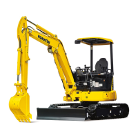
2.
Check that the work equipment is in a stable condition,
then operate the control grip (g) of the lock lever to set it to
LOCK position (L).
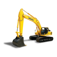
3.
Place a bar on the head of pin (1), hit the bar with a ham-
mer to knock out the pin, then remove tooth (2).
REMARK
If it cannot be removed by this method, ask your Komatsu
distributor to have the replacement performed.
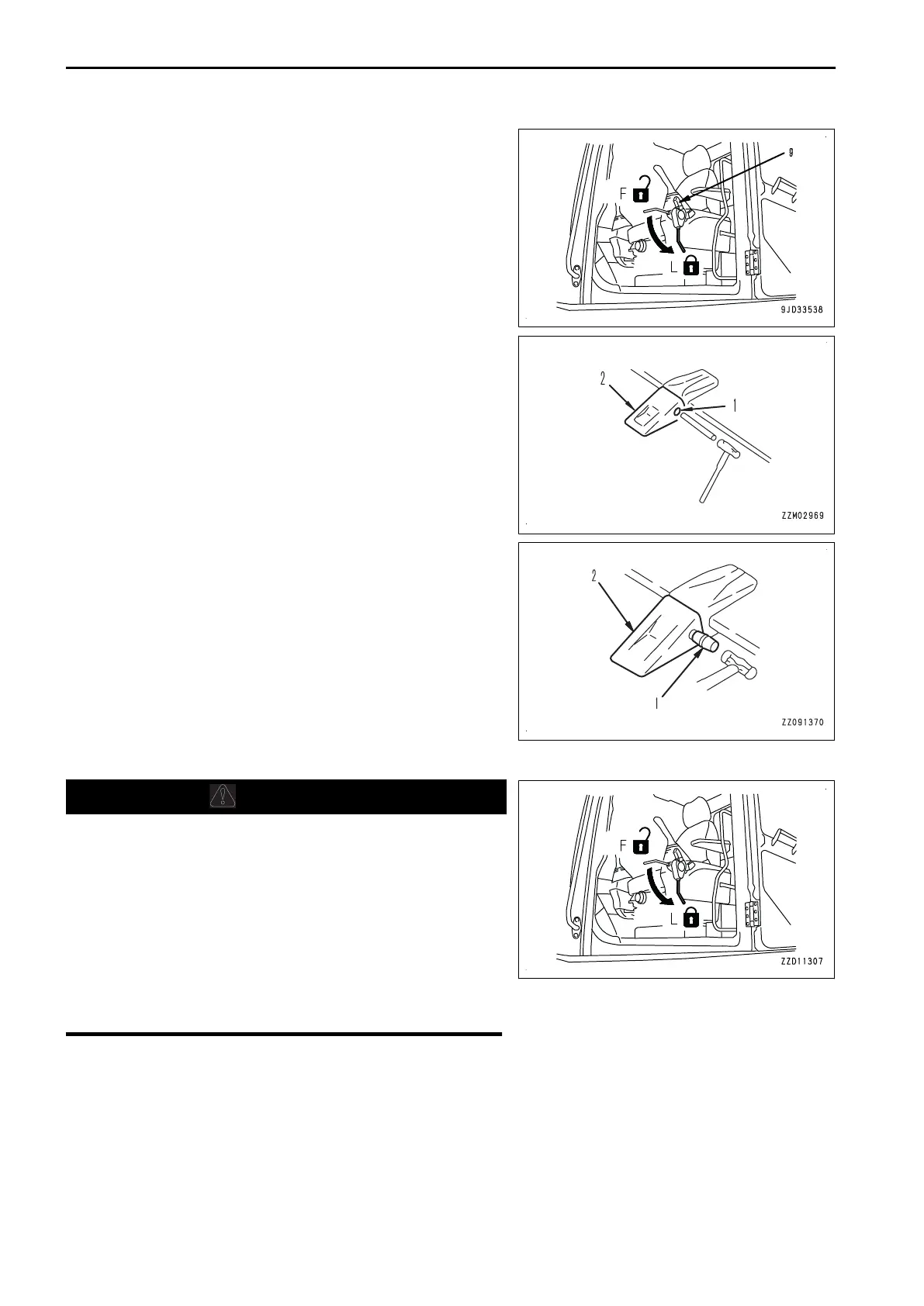
4.
Clean the mounting face. Fit a new tooth (2) in the adapter,
push in pin (1) partially by hand, then lock it with a hammer
to install the tooth to the bucket.
METHOD FOR REPLACING BUCKET SIDE CUTTER AND SHROUD
WARNING
It is dangerous if the work equipment moves by mistake
when replacing the side cutter and shroud of the bucket.
Set the work equipment in a stable condition, and stop the
engine. Then set the lock lever securely to LOCK position
(L).
As the pin is driven out with strong force, it is dangerous
that the pin may fly out. Check that there are no people in
the surrounding area.
Broken pieces may fly during the replacement work, so al-
ways wear the protective equipment such as protective
eyeglasses and gloves.
MAINTENANCE PROCEDURE MAINTENANCE
4-30

 Loading...