Repair manual KTM 125 / 200
Art No 3.206.005 -E
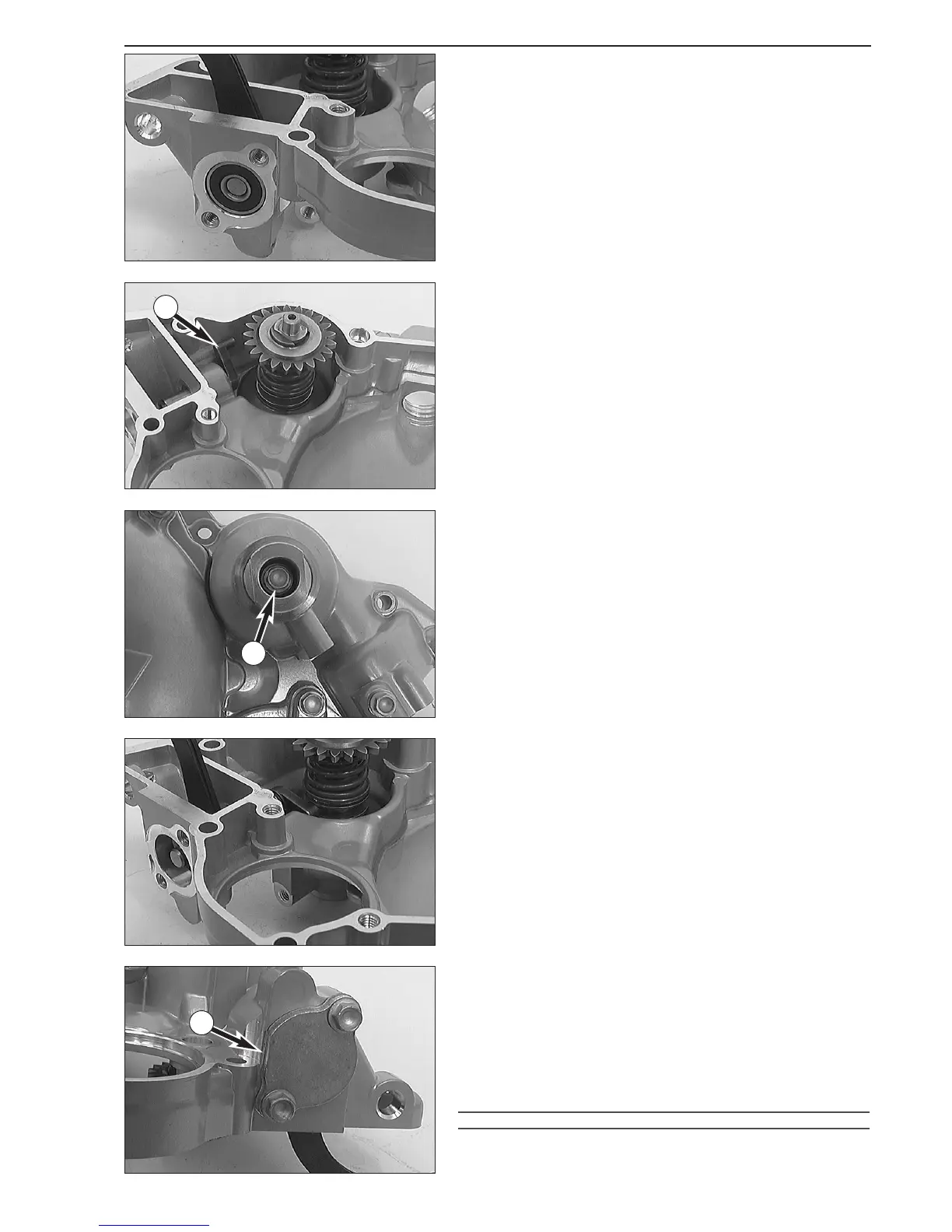
Dismounting the exhaust control system in the clutch
cover, and checking parts for wear.
– Undo 2 bolts 1 and remove the closure cap 2 together with the
gasket and the copper seal rings.
–Press the grooved ball bearing
3 below out of the clutch cover. For
this purpose, push the rocker arm
4 of the centrifugal timer forward
(in the direction of the grooved ball bearing).
–Turn the adjusting lever
5 so that it rests against the clutch cover
(see illustration).
– Undo the bolt
6 and pull the rocker arm 4 off the adjusting lever 5.
– Undo the collar bolt
7 of the centrifugal timer bk and pull the
centrifugal timer inwards out of the clutch cover.
– Pull the adjusting lever
5 out of the clutch cover.
– Clean all parts and check for wear.
Adjusting lever
5
Check the pins of the adjusting lever for wear. Check the bearing surface
between the adjusting lever and the needle bushing for wear.
Grooved ball bearing
3
Check for wear.
Needle bushing of the adjusting lever
9
The bearing bushing of the adjusting lever normally shows no signs of
wear. If this is nevertheless the case, it is recommended to replace the
entire clutch cover.
Shaft seal ring of the kickstarter shaft
8
Lever the used shaft seal ring out of the clutch cover with a screwdriver.
Grease the new shaft seal ring and insert it with the open side facing
inwards. Press it in flush.
Centrifugal timer
bk
The centrifugal advance device is factory-preset and must not be
disassembled.
Preassembling the clutch cover
–Grease the bearing 9 of the adjusting lever, insert the adjusting lever
5 into the clutch cover and let it rest against the clutch cover (see
illustration).
– Fix the centrifugal timer with the bolt in the clutch cover. Secure the
bolt with Loctite 243.
NOTE: The bolt
7 is tightened after mounting the clutch cover.
– Hook the pins of the adjusting lever
5 into the track of the
centrifugal timer.
– Mount the rocker arm
4 on the adjusting lever 6 and fix it with a
bolt.
– Insert the grooved ball bearing with the open side of the cage facing
inwards into the clutch cover.
– Mount the cover
2 with a new gasket and new copper gaskets.
!
CAUTION
!
W
HEN MOUNTING THE COVER
2,
MAKE SURE THAT THE FLAT SECTION
A IS
CORRECTLY ALIGNED SO AS TO PREVENT DAMAGING OF THE CLUTCH COVER
.
5-10C
A
7
5
 Loading...