7-5C
Repair manual KTM 125 / 200
Art No 3.206.005 -E
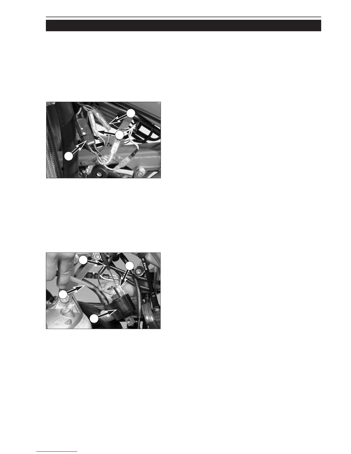
Check the pulse generator for an output signal – two-pin connector 1
with green and red cable colors (also see circuit diagram on opposite
page):
– Apply the red measuring lead of the peak voltage adapter to the
green cable and the black measuring lead to the red cable, disconnect
both connectors
1 to disconnect the CDI unit 2
Multimeter display: 6 volts +/- 1 volt
– Same measurement with CDI unit connected
Multimeter display: 3 volts +/- 1 volt
Check the generator charging coil for ignition capacitor charge for
output voltage – two-pin connector
3 with black/red and red/white
cable colors (also see circuit diagram on opposite page):
– Apply the red measuring lead of the peak voltage adapter to the
black/red cable and the black measuring lead to the red/white cable,
disconnect connector
3 to disconnect the CDI unit 2
Multimeter display: 35 volts +/- 5 volts
– Same measurement with connectors CDI unit connected
Multimeter display: 200 volts +/- 10 volts
Check the primary voltage output
4 for ignition coil control (also see
circuit diagram on opposite page) for output voltage (blue/white cable
color):
– Apply the red measuring lead
R of the peak voltage adapter to the
black/white cable (ground) and the black measuring lead
S to the
blue/white cable, CDI unit 2 and ignition coil 5 connected
Multimeter display: 200 volts +/- 10 volts
NOTE: the ignition coil does not need to be removed to measure.
STATIC IGNITION VALUES 125-200 SX, MXC, EXC (KOKUSAN 2K-1, 2K-3)
Measuring conditions:
– cold engine
– seat and tank removed
– all connectors and the ground connection in a non-corroding condition, connectors tightly connected
– spark plug screwed out and spark plug connector attached to ground
– light switch turned off
– the gap between the rotor and pulse generator must be set to 0.75 mm
– kick the kick starter forcefully at least 5 times for each measurement
3
5
4
S
R
1
1
 Loading...