7-2C
Checking the voltage regulator-rectifier (Shindengen)
– Start the engine and switch on the low beam.
– Connect a voltmeter to the two terminals of the capacitor (red/white
cable = positive, brown cable = negative).
– Accelerate the engine to a speed of 5000 r.p.m. and read off the
voltage.
Nominal value: 14.0 - 15.0 V
In the case of a significant deviation from the nominal value:
– Check the capacitor
– Check the connector between the stator and the voltage regulator-
rectifier and between the voltage regulator and the cable tree.
– Check the stator.
– Replace the voltage regulator-rectifier.
Checking the voltage regulator (Kokusan)
A defect voltage regulator can cause different kinds of trouble:
● No voltage in the circuit
In this case, the voltage regulator must be disconnected at idle speed.
The voltage regulator is defect if the power consumers now work
properly.
If the power consumers are still not supplied with power, the switch,
the wiring harness or the ignition system must be checked for defects.
● Excessive voltage in the circuit
The bulbs burn out. In this case the voltage regulator must be
replaced.
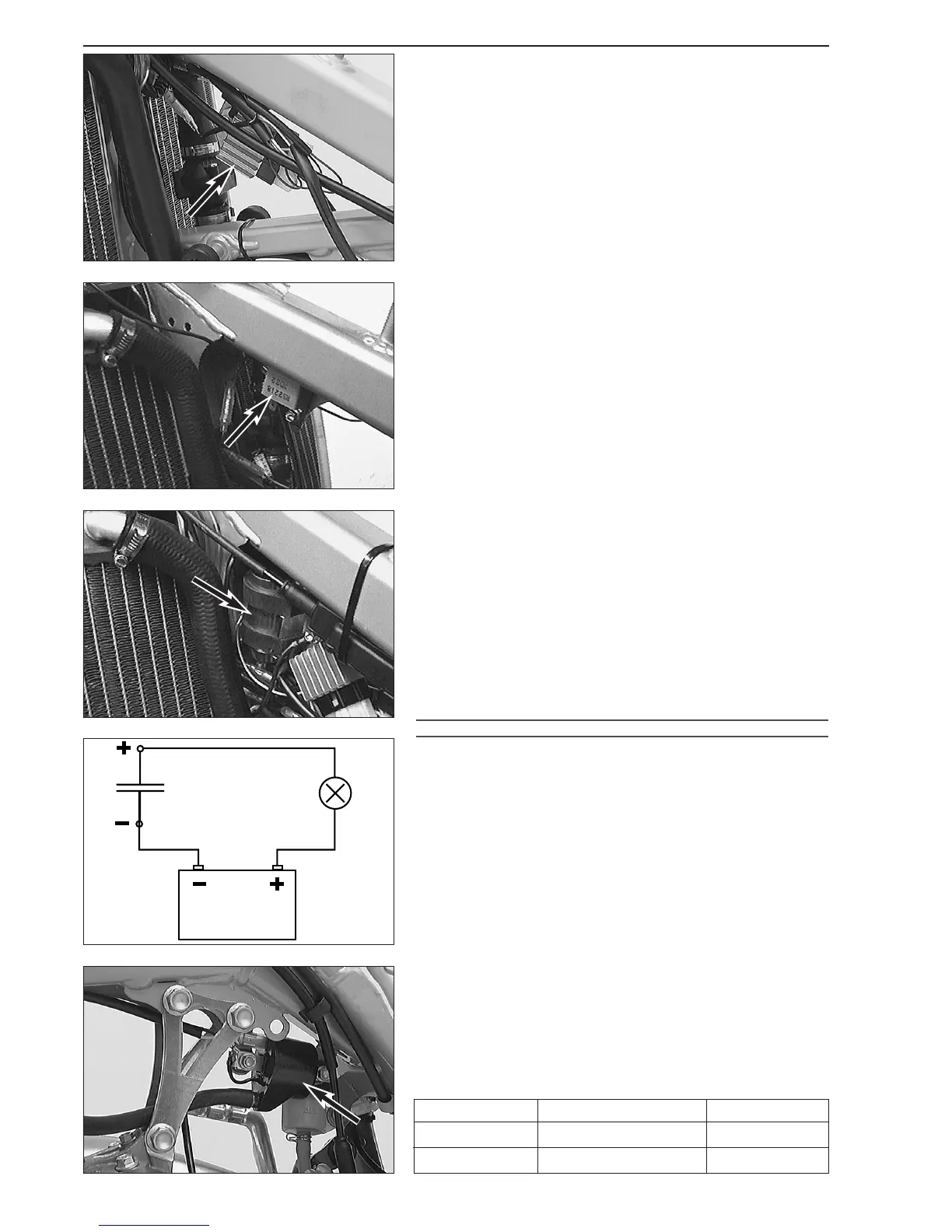
Checking the capacitor
– Discharge the capacitor by bridging the two terminals with a
screwdriver and remove.
– Connect the negative pole of a 12V battery with the negative
terminal of the capacitor. The connection between the positive pole
of the battery and the positive terminal of the capacitor (marked +) is
made with a test lamp
3.
– When the power circuit is closed, the test lamp must begin to light
up. As capacitor charging increases, the brightness of the test lamp
must decrease.
– The test lamp must go out after 0,5-2 seconds (depending on the
lamp capacity).
– If the test lamp does not go out or does not light up at all, the
capacitor is faulty.
!
CAUTION
!
DISCHARGE THE CAPACITOR BEFORE AND AFTER EACH TEST.
W
HEN INSTALLING THE CAPACITOR, MAKE SURE THAT THE TERMINALS ARE
CONNECTED IN ACCORDANCE WITH THEIR MARKINGS
(CONNECT RED/WHITE CABLE
TO
+ TERMINAL).
Ignition coil
– Disconnect all cables and remove the spark plug connector.
– Use an ohmmeter to measure the following values.
NOTE: The indicated setpoint values correspond to a temperature
of 20° C.
Replace the ignition coil if the measured values deviate significantly from
the setpoint values.
Measure Cable colours Resistance
primary coil blue/white – ground 0,425 - 0,575 Ω
secondary coil blue/white – ignition wire 10,80 - 16,20 kΩ
3
 Loading...