MAINTENANCE WORK ON CHASSIS AND ENGINE 66
B00042-10
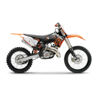
– Inject the liquid into the system until it escapes from hole of the master
cylinder without bubbles.
– To prevent overflow, drain fluid occasionally from the master cylinder reservoir.
– Remove the bleeding syringe. Mount and tighten the bleeder screw.
– Correct the fluid level of the hydraulic clutch.
Guideline
Fluid level under top edge of con-
tainer
4 mm (0.16 in)
– Position the cover with the membrane. Mount and tighten the screws.
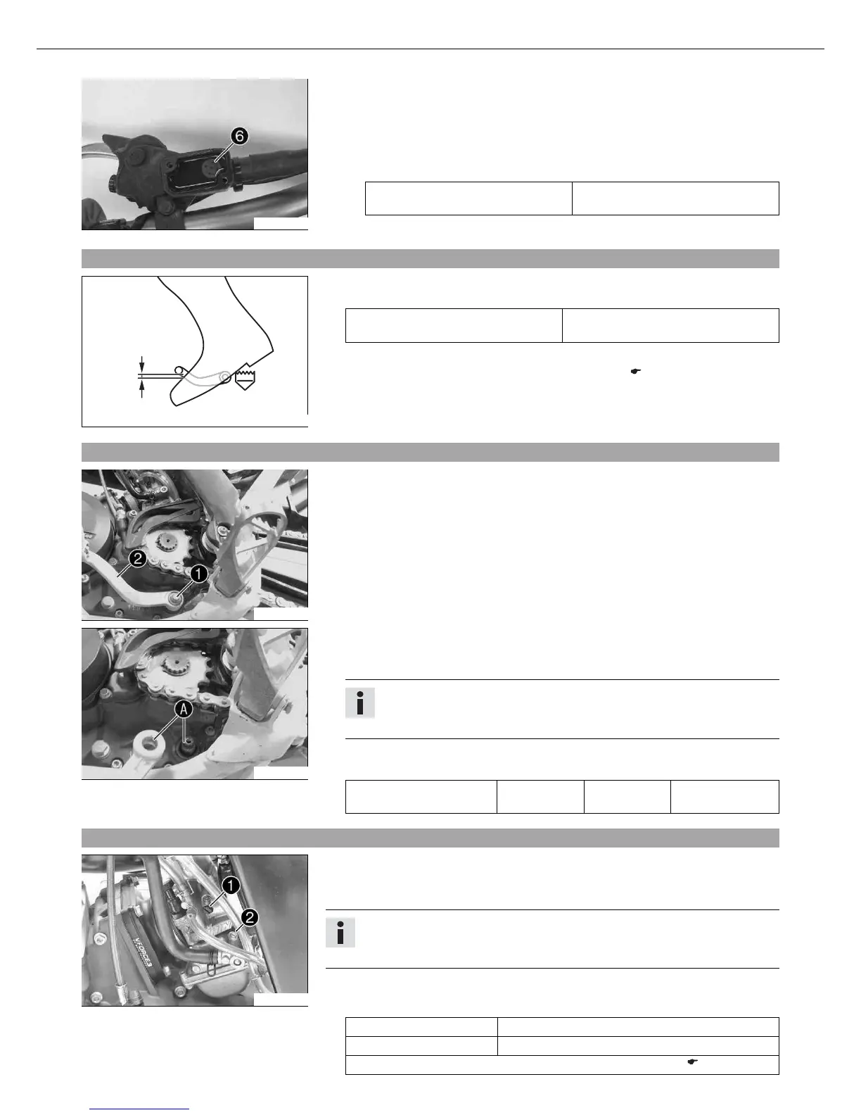
9.97Checking the basic position of the shift lever
400692-10
– Sit on the vehicle in the riding position and determine the distance between the
upper edge of your boot and shift lever .
Distance between shift lever and upper
edge of boot
10… 20 mm (0.39… 0.79 in)
» If the distance does not meet specifications:
–
Adjust the basic position of the shift lever. x ( p. 66)
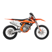
9.98Adjusting the basic position of the shift lever x
B00065-10
– Remove screw and remove shift lever .
B00066-10
– Clean gear teeth of the shift lever and shift shaft.
– Mount the shift lever on the shift shaft in the required position and engage the
gearing.
Info
When positioning the shift lever, ensure that there is sufficient distance to
the adjacent components.
– Mount and tighten the screw.
Guideline
Screw, shift lever M6 14 Nm
(10.3 lbf ft)
Loctite
®
243™
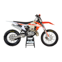
9.99Carburetor
B00048-11
The idle setting of the carburetor has a big influence on the starting behavior, idling
stability and the response to opening of the throttle. An engine with a correctly set idle
speed is easier to start than if the idle is set wrongly.
Info
The carburetor and its components are subject to increased wear caused by
engine vibration. Wear can result in malfunctioning.
The carburetor factory settings are as follows.
(125 SX, 150 SX)
Altitude above sea level 500 m (1,640 ft)
Ambient temperature 20 °C (68 °F)
Super unleaded gasoline, mixed with 2-stroke engine oil (1:40) ( p. 95)