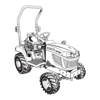
(1) Seat
(2)
PT
O clutch lever
(3) PTO select lever
(A) On
(B) Off
NOTE :
• If the
PTO clutch lever is shifted to the on
(engage)
position under the following
condition, the engine will stop itself.
– The speed-control-pedal is not in the neutral
position.
– The PTO-select-lever is not in the rear PTO
position.
– The seat is not tilted forward.
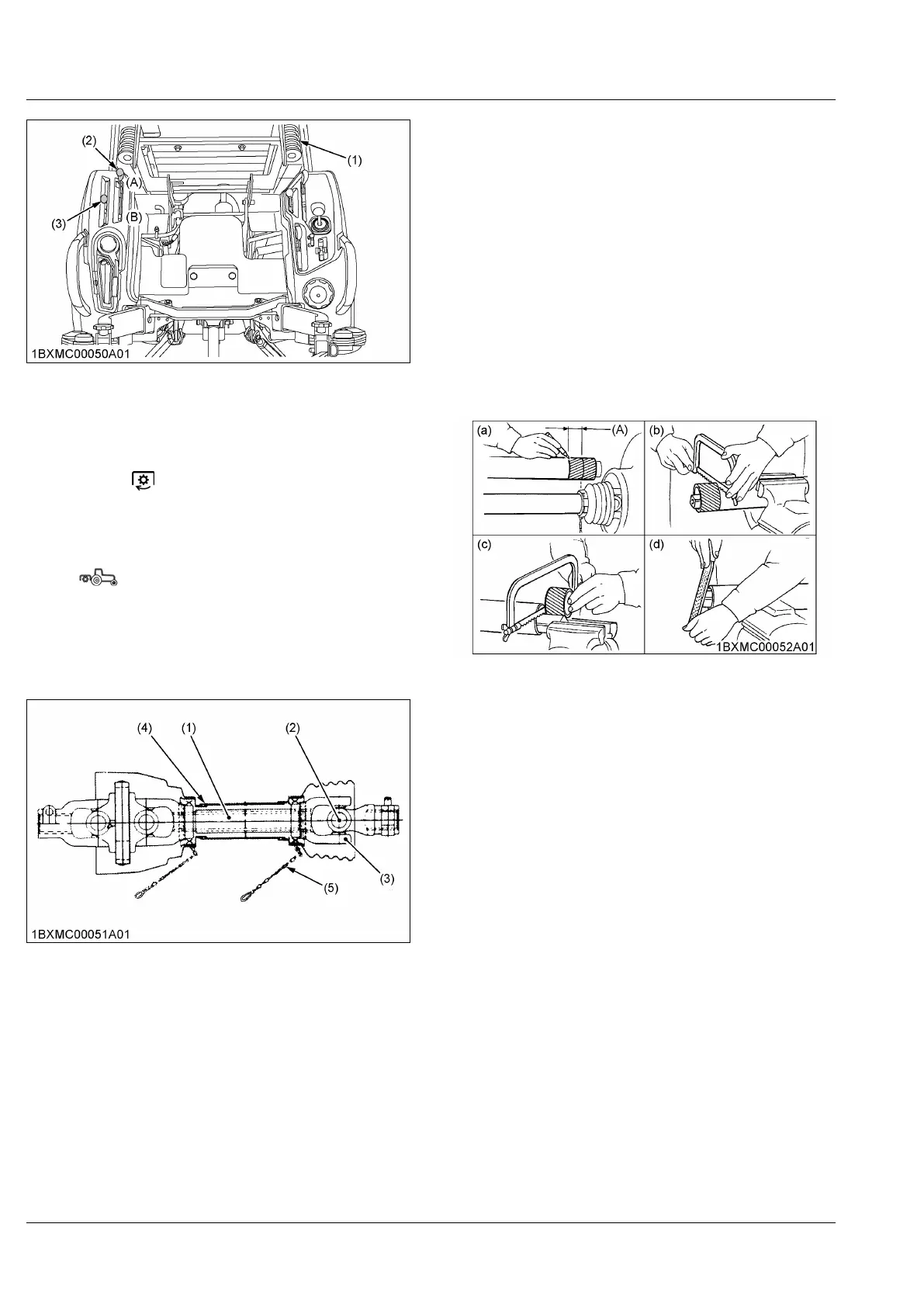
5. PT
O drive shaft
The PTO-drive-shafts are designed for specific
machines and power requirement.
(1) Inner and outer sliding profile
tubes
(2) Journal cross assy
(3)
Fitting yoke
(4) Safety guard (in, out)
(5)
Chain
• When using a PTO-drive-shaft, read the
operator's
manual of the implement before operating the
implement.
• If it is necessary for using the PTO-drive-shaft,
adjust the length of it.
See 5.1 Adjusting the length of PTO drive shaft on
page 54.
• Make sure that the PTO-drive-shaft is securely
connected at both ends before operating it.
5.1 Adjusting the length of PTO drive shaft
To adjust the length of the PTO-drive-shaft, refer to the
following instructions.
1. To
adjust the inner-and-outer-guard-tubes, hold the
half shafts next to each other in the shortest
working position, and mark the half shafts in the
shortest working position of the inner-and-outer-
guard-tubes.
2. Shorten the inner-and-outer-guard-tubes to the
marked position equally.
3. Shorten the inner-and-outer-sliding-profile-tubes by
the same length as the inner-and-outer-guard-
tubes.
4. Round all sharp edges off, remove burrs, and
grease sliding profiles.
(a) Reference image for step 1.
(b) Reference image for step 2.
(c)
Reference image for step 3.
(d) Reference image for step 4.
(A) 40 mm (1.57 in.)
PTO (POWER TAKE-OFF) PTO OPERATION
 Loading...