ASSEMBLY INSTRUCTIONS18
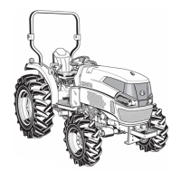
3. Connect the check chain (6) to the ROPS (7), using
the set pins (8), plain washers (10) and split pins (9)
both sides (right and left side).
4. Split the split pins securely both sides.
BFender and Reflector
C Tools required
Pliers, spanner (8 mm, 12 mm) or socket with ratchet
wrench or impact wrench, torque wrench and screwdriver.
1. Assemble the fender supports (10) to the fender
support RH and LH (8).
C Tightening torque
A Do not tighten up the all the bolts and nuts to mount
the fenders before to install them all temporally.
Otherwise it makes difficult to assemble the fenders.
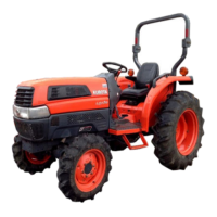
2. Insert the cushion (1) to the holes "C" on the fender (2)
as shown in the photo below and figure below.
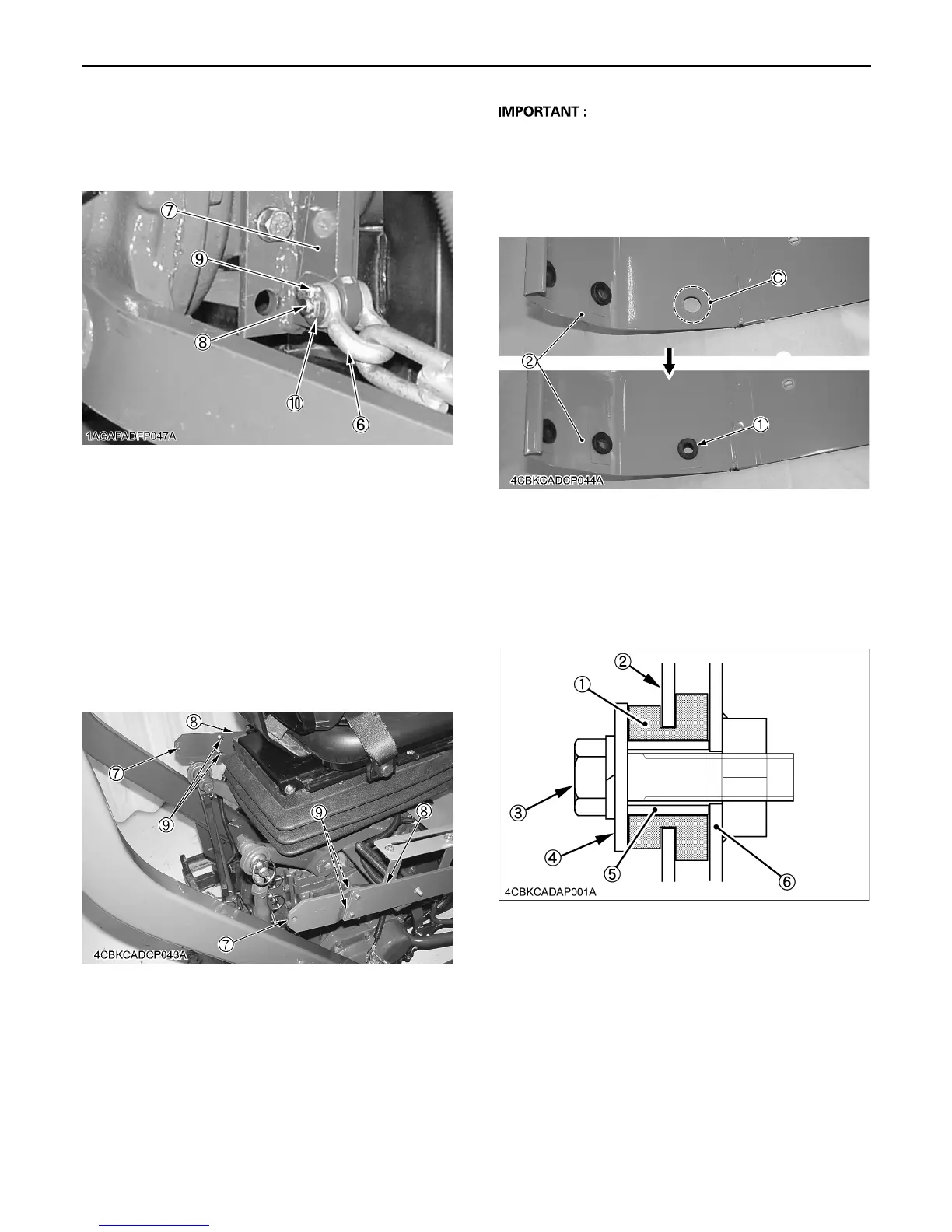
3. Install the fender RH and LH to the tractor by using the
flange nut (7).
4. Install the collars (5) into the rubber and then
assemble the plain washer (4) and bolts (3). There
three rubber cushion mount of one side.
(6) Check chain
(7) ROPS
(8) Set pins
(9) Split pins
(10) Plain washers
(8) Fender support RH and LH
(9) Flange bolt (M8 x 16)
(10) Fender support
Bolt (M8) : 23.6 to 27.4 N-m
2.4 to 2.8 kgf-m
17.4 to 20.2 ft-lbs
(1) Cushion
(2) Fender
(1) Cushion
(2) Fender
(3) Bolt (M8 x 30)
(4) Plain washer
(5) Collar
(6) Step

 Loading...