ASSEMBLY INSTRUCTIONS32
BFront Bumper and Front Hitch
C Tools required
Spanner (14 mm, 19 mm) or socket with ratchet wrench,
impact wrench and torque wrench.
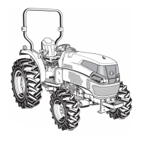
1. Assemble the front bumper (1) to the front axle frame,
securely with correct tightening torque.
C Tightening torque
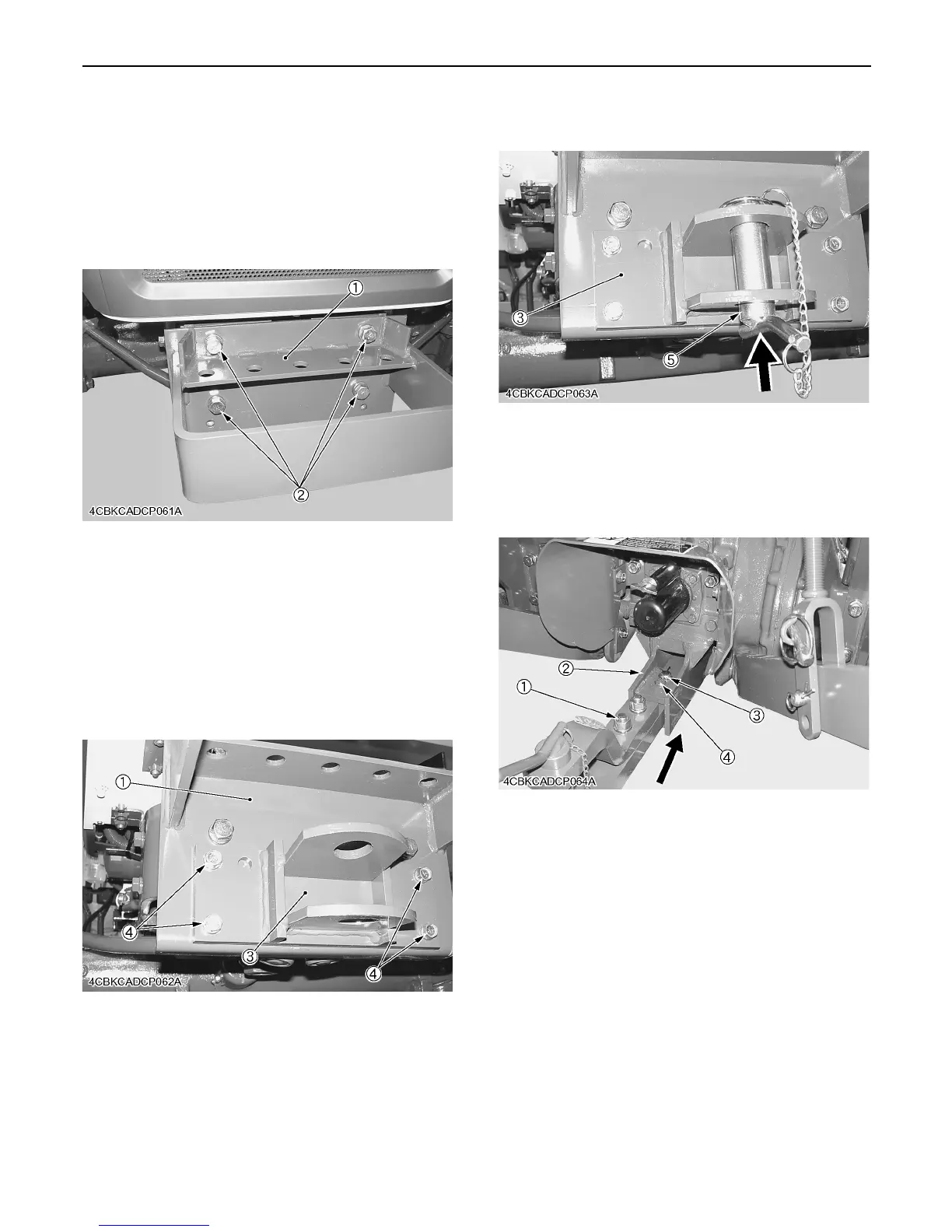
2. Assemble the front hitch (3) to the front bumper (1)
securely.
C Tightening torque
3. Install the front hitch pin (5) from the lower side.
BDrawbar
1. Install the drawbar (1) to the drawbar frame (2) by
using the joint pin (3) and snap pin (4).
(1) Front bumper
(2) Bolt (M14 x 35, 9T)
Bolt (M14) : 124 to 147 N-m
12.6 to 15.0 kgf-m
91.2 to 108.0 ft-lbs
(1) Front bumper
(3) Front hitch
(4) Bolt (M10 x 35)
Bolt (M14) : 48.1 to 55.8 N-m
4.9 to 5.7 kgf-m
35.5 to 41.2 ft-lbs
(3) Front hitch
(5) Front hitch pin
(1) Drawbar
(2) Drawbar frame
(3) Joint pin
(4) Snap pin

 Loading...