36 HYDRAULIC UNIT
HYDRAULIC UNIT
A Do not operate until the engine is warmed up. If
operation is attempted when the engine is still cold, the
hydraulic system may be damaged.
A If noises are heard when implement is lifting after the
hydraulic control lever has been activated, the
hydraulic mechanism is not adjusted properly. Unless
corrected, the unit will be damaged. Contact your
KUBOTA Dealer for adjustment.
3-POINT HITCH CONTROL SYSTEM
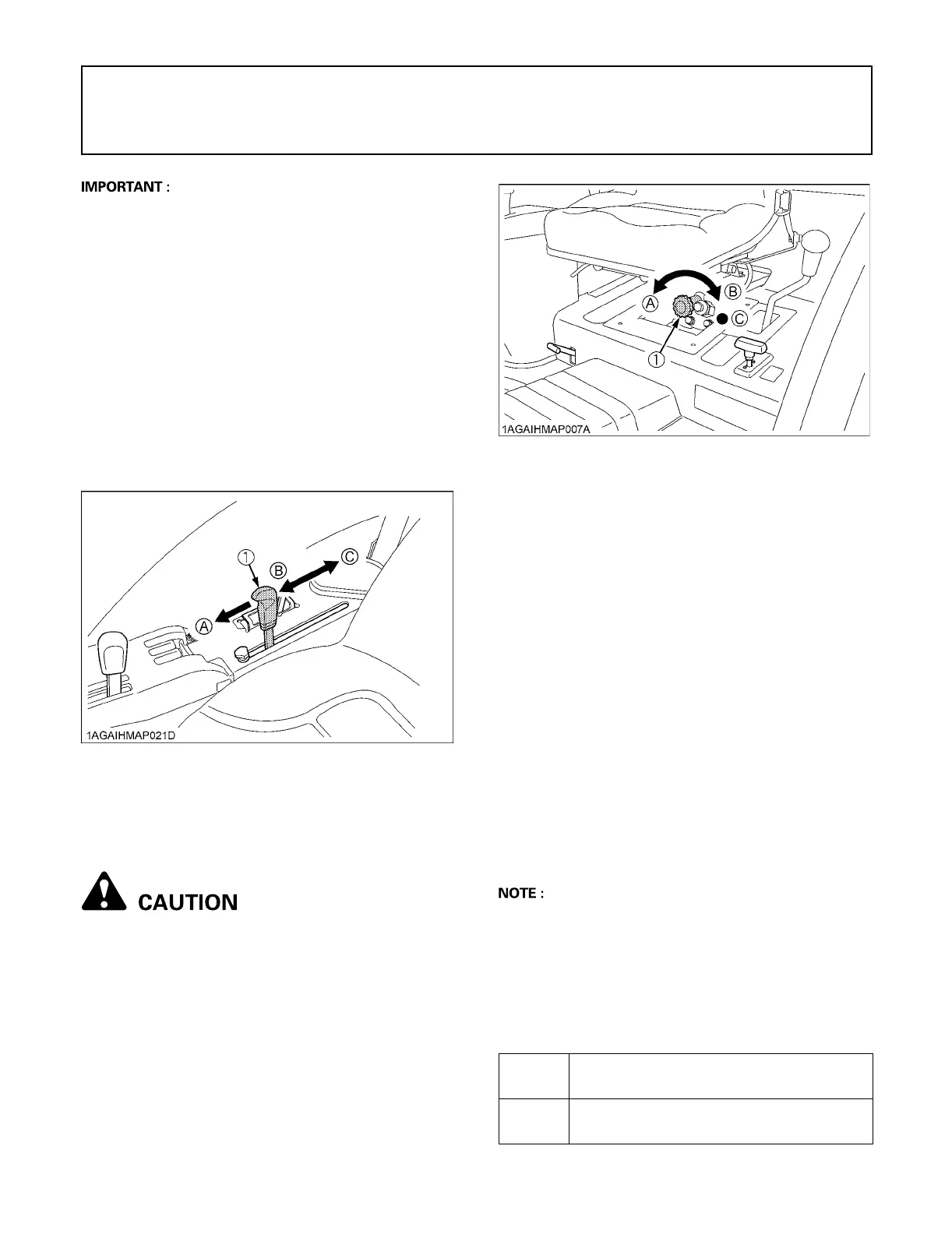
BPosition Control
C Hydraulic control lever
This will control the working depth of 3-point hitch
mounted implement regardless of the amount of pull
required.
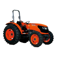
B3-point Hitch Lowering Speed
To avoid personal injury:
A Fast lowering speed may cause damage or
injury. Lowering speed of implement should be
adjusted to two or more seconds.
The lowering speed of the 3-point hitch can be controlled
by adjusting the 3-point hitch lowering speed knob.
REMOTE HYDRAULIC CONTROL SYSTEM
(if equipped)
The hydraulic auxiliary control valves can be installed up
to triple segments.
BRemote Control Valve
There are two types of remote valves available for these
models.
A Double acting valve with detents and self cancelling:
This valve may be placed in the detent mode. The
lever will stay in this position until the pressure reaches
a predetermined level or a cylinder reaches the end of
its stroke. Then it will automatically return to neutral
A Double acting valve with float position:
This valve may be placed in the float mode with the
control lever all the way forward. The cylinder is free to
extend or retract, letting an implement such as a
loader bucket follow the ground.
A This float valve can not be attached as the first
segment.
BRemote Control Valve Lever
The remote control valve lever directs pressurized oil flow
to the implement hydraulic system.
[Example: Installing triple segment valves]
(1) Position control lever (A) "FLOAT"
(B) "DOWN"
(C) "UP"
(1) 3-point hitch lowering speed knob (A) "FAST"
(B) "SLOW"
(C) "LOCK"
1st
Double acting valve with detents and self
cancelling
2nd
3rd
Double acting valve with float position
 Loading...