Home
Kubota
Tractor
M7040SU
Kubota M7040SU User Manual
4
of 1
of 1 rating
90 pages
Give review
Manual
Specs
To Next Page
To Next Page
To Previous Page
To Previous Page
Loading...
38
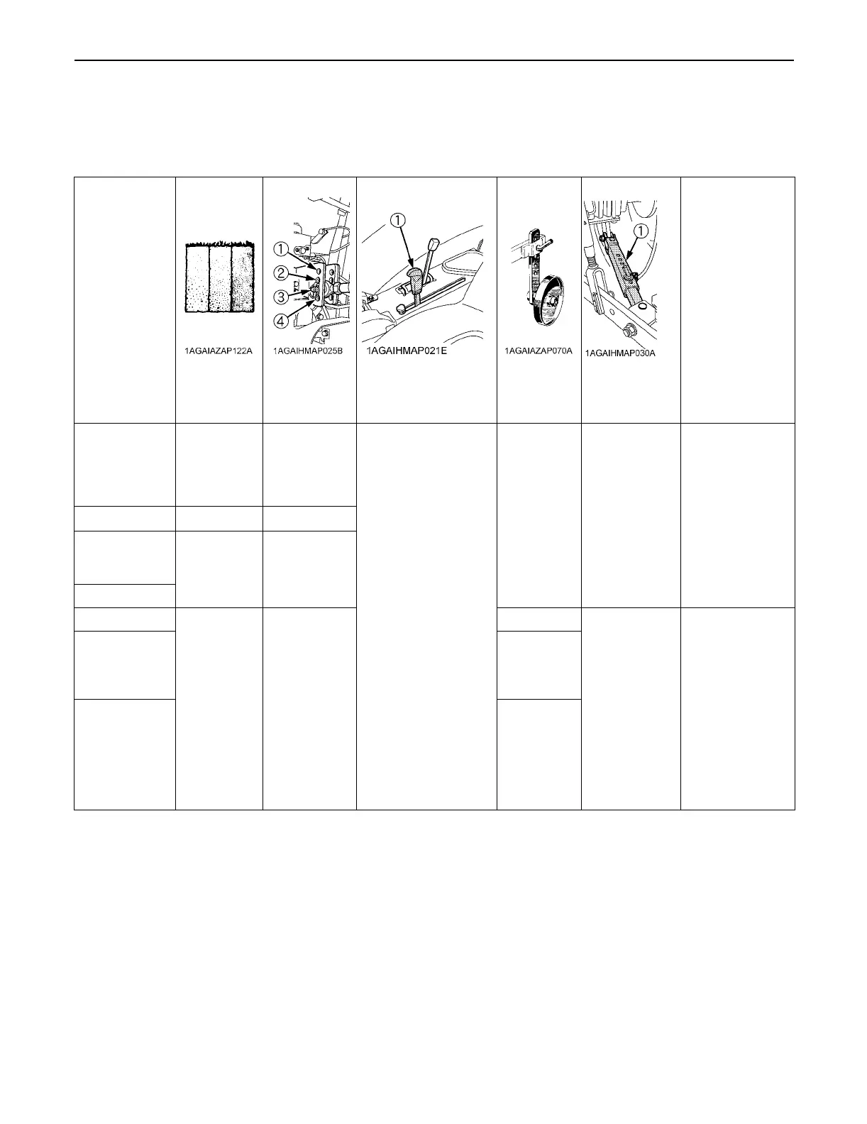
HYDRAULIC UNIT
B
Hydraulic Control U
nit Use Reference Chart
In order to handle the hydraulics properly, the operator must be familiar with the following.
Though this information may not be applicable to all types of implements and soil conditions, it
is useful for general
conditions.
Implement
Remarks
Soil condition
Top link
mounting hole
s
(1) Position cont
rol lever
Gauge wheel
(1) Telescopic
stabilizers
Moldboard plow
Light soil
Medium soil
Heavy soil
3 or 4
2 or 3
2 or 3
Position control
YES/NO
Loose
Insert the set-pin
through the slo
t on
the outer tube
that
align with one
of
the holes on the
inner bar.
For impl
ements
with gauge
wheels,
lower the position
control lever all
way.
Disc plow
---
2, 3 or 4
Harrow (spike,
springtooth, disc
type)
---
2 or 3
Sub-soiler ..
.
Weeder, ridger...
---
3
YES
Tighten
Telescopic
stabilizer should be
tight enough to
prevent excessive
imple
ment
movement when
implem
ent is in
raised position.
For impl
ements
with gauge
wheels,
lower the position
control lever all
way.
Earthmover,
digger, scraper,
manure fork,
rear carrier.......
YES/NO
Mower (mid-and
rear-mount type)
Hayrake,
tedder..
....
NO
55
57
Table of Contents
Table of Contents
5
Safe Operation
19
Servicing of Tractor
19
Specifications
20
Specification Table
20
Traveling Speeds
22
Implement Limitations
23
Instrument Panel and Controls
25
Pre-Operation Check
28
Daily Check
28
Operating the Engine
29
Starting the Engine
29
Cold Weather Starting
31
Stopping the Engine
31
Warming up
31
Warm-Up and Transmission Oil at Low Temperature Range
31
Jump Starting
32
Operating the Tractor
33
Operating New Tractor
33
Do Not Operate the Tractor at Full Speed for the First 50 Hours
33
Changing Lubricating Oil for New Tractors
33
Operating Foldable Rops
33
To Fold the ROPS
33
To Raise the ROPS to Upright Position
34
Adjustment of Foldable ROPS
34
Starting
35
Operator's Seat
35
Seat Belt
35
Light Switch
35
Turn Signal / Hazard Light Switch
36
Brake Pedals (Right and Left)
36
Clutch Pedal
37
Main Gear Shift Lever
38
Range Gear Shift Lever
38
Front Wheel Drive Lever
38
Hand Throttle Lever
39
Foot Throttle
39
Parking Brake Lever
39
Stopping
40
Check During Driving
40
Immediately Stop the Engine if
40
Easy Checker(TM)
40
Fuel Gauge
40
Coolant Temperature Gauge
41
Tachometer
41
Pto Tachometer / Hourmeter
42
Changing Display Mode
42
PTO Speed Display Mode Switching
44
Parking
45
Operating Techniques
45
Differential Lock
45
Operating the Tractor on a Road
46
Operating on Slopes and Rough Terrain
46
Directions for Use of Power Steering
46
Trailer Electrical Outlet
46
Electrical Outlet
47
Pto
48
Pto Operation
48
PTO Clutch Control Lever
48
LCD Monitor Message
49
PTO Shaft Cover and Shaft Cap
49
Three-Point Hitch & Drawbar
50
3-Point Hitch
51
Category 1 & 2
51
Selecting the Holes of Lower Links
51
Selecting the Top Link Mounting Holes
51
Drawbar
51
Lifting Rod (Right)
52
Top Link
52
Telescopic Stabilizers
52
Drawbar
53
Swing Drawbar
53
Hydraulic Unit
54
3-Point Hitch Control System
54
Position Control
54
3-Point Hitch Lowering Speed
54
REMOTE HYDRAULIC CONTROL SYSTEM (if Equipped)
54
Remote Control Valve
54
Remote Control Valve Lever
54
Remote Control Valve Coupler Connecting and Disconnecting
55
Hydraulic Control Unit Use Reference Chart
56
Tires, Wheels and Ballast
57
Tires
57
Inflation Pressure
57
Dual Tires
57
Wheel Adjustment
57
Front Wheels (with Two Wheel Drive)
57
Front Wheels (with Four Wheel Drive)
59
Rear Wheels
60
Ballast
61
Front Ballast
61
Rear Ballast
61
Maintenance
63
Service Intervals
63
Lubricants, Fuel and Coolant
65
Periodic Service
67
How to Open the Hood
67
Hood
67
Daily Check
67
Walk Around Inspection
67
Checking and Refueling
68
Checking Water Separator
68
Checking Engine Oil Level
68
Checking Transmission Fluid Level
69
Checking Coolant Level
69
Cleaning Evacuator Valve
69
Checking Dust Indicator
70
Cleaning Grill and Radiator Screen
70
Checking Brake Pedals and Clutch Pedal
70
Checking Gauges, Meter and Easy Checker(TM)
70
Checking Head Light, Turn Signal / Hazard Light Etc
70
Checking Seat Belt and ROPS
70
Every 50 Hours
71
Checking Engine Start System
71
Checking Wheel Bolt Torque
71
Every 100 Hours
72
Lubricating Grease Fittings
72
Cleaning Air Cleaner Primary Element
73
Adjusting Fan Belt Tension
73
Adjusting Alternator Belt Tension
74
Checking Fuel Line
74
Adjusting Clutch Pedal
74
Adjusting Brake Pedal
75
Checking Battery Condition
75
Every 200 Hours
77
Checking Radiator Hose and Clamp
77
Checking Intake Air Line
77
Checking Power Steering Line
77
Adjusting Toe-In
78
Draining Fuel Tank Water
79
Every 300 Hours
79
Replacing Hydraulic Oil Filter
79
Every 400 Hours
80
Changing Engine Oil
80
Replacing Engine Oil Filter
80
Replacing Fuel Filter Element
81
Replacing Fuel Filter
81
Cleaning Water Separator
81
Lubricating Grease Fitting [2WD Model]
82
Every 600 Hours
82
Changing Transmission Fluid
82
Changing Front Axle Gear Case Oil & Front Differential Case Oil
82
Adjusting Front Axle Pivot
83
Every 800 Hours
83
Adjusting Engine Valve Clearance
83
Every 1500 Hours
83
Checking Fuel Injection Nozzle (Injection Pressure)
83
Every 3000 Hours
83
Checking Injection Pump
83
Every 1 Year
83
Replacing Air Cleaner Primary Element and Secondary Element
83
Every 2 Years
84
Flushing Cooling System and Changing Coolant
84
Antifreeze
84
Replacing Radiator Hose (Water Pipes)
85
Replacing Power Steering Hose
85
Replacing Fuel Hose
85
Replacing Intake Air Line
85
Service as Required
85
Bleeding Fuel System
85
Replacing Fuse
86
Replacing Light Bulb
87
Replacing Head Lamp
87
Storage
88
Tractor Storage
88
Removing the Tractor from Storage
88
Troubleshooting
89
Engine Troubleshooting
89
Options
90
4
Based on 1 rating
Ask a question
Give review
Questions and Answers:
Need help?
Do you have a question about the Kubota M7040SU and is the answer not in the manual?
Ask a question
Kubota M7040SU Specifications
General
Engine Type
Diesel
Hydraulic System
Open center
PTO Power
62 HP
Displacement
148.5 cu in
Transmission
8x4
Wheelbase
82.7 inches
3-Point Hitch
Category II
Related product manuals
Kubota M7040SUHD
25 pages
Kubota M7040
45 pages
Kubota M7060
145 pages
Kubota M7131
298 pages
Kubota M7132
332 pages
Kubota M7151
298 pages
Kubota M7171
298 pages
Kubota M7-132
310 pages
Kubota M7-152
310 pages
Kubota M7-172
310 pages
Kubota M126X
24 pages
Kubota M5040
559 pages
 Loading...