4-M4
ZD18(F) · ZD21(F) · ZD28(F), WSM
HYDRAULIC SYSTEM
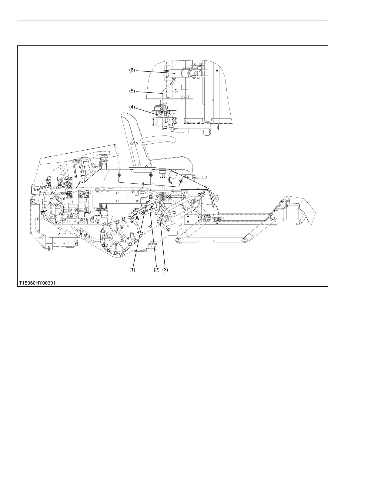
3. HYDRAULIC CONTROL VALVE AND VALVE ADAPTOR
The hydraulic system consists of the control valve (3), control valve adaptor (4), lift cylinder (6) and etc..
Filtered oil is forced out by the hydraulic pump to the control valve (3) through the delivery pipe (2).
The control valve switches the oil flow, and oil is channeled to the lift cylinder (6) or returned to the transmission
case (hydrostatic transmission charge line) through the return pipe.
(1) Return Pipe
(2) Delivery Pipe
(3) Control Valve
(4) Control Valve Adaptor
(5) Cylinder Hose
(6) Lift Cylinder
A: From Hydraulic Pump
B: To Transmission Case
 Loading...