5-M5
ZD18(F) · ZD21(F) · ZD28(F), WSM
ELECTRICAL SYSTEM
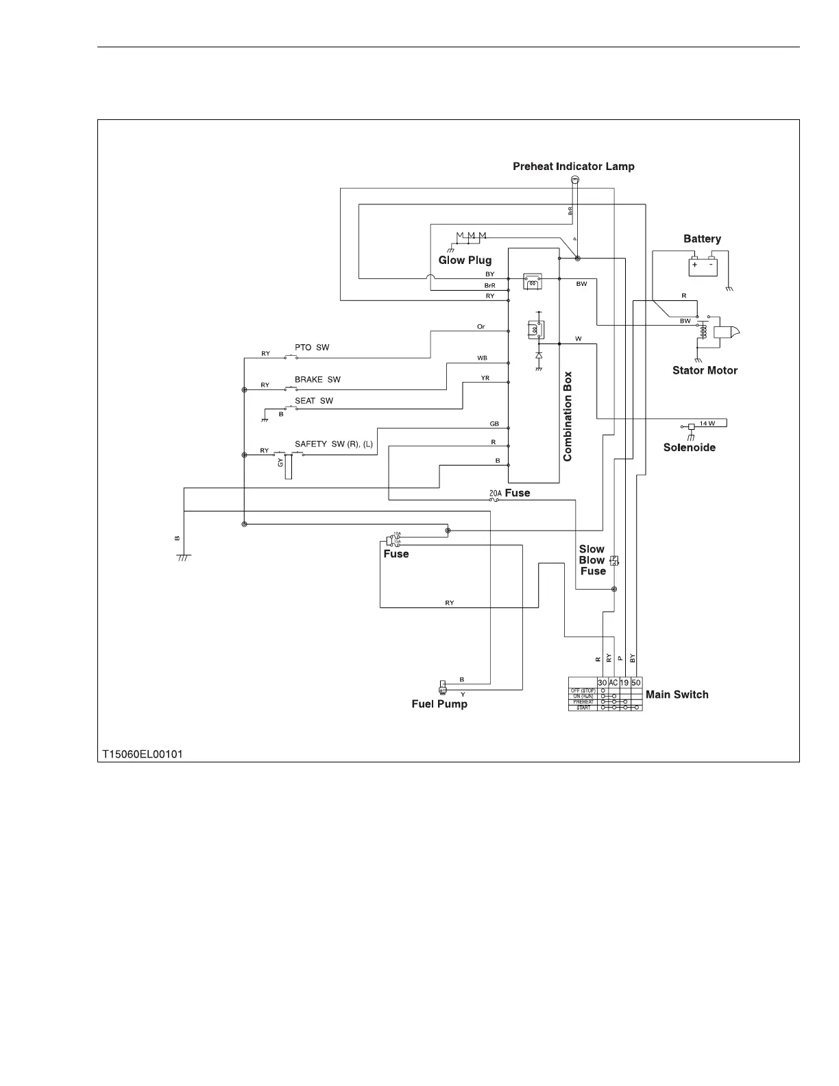
2. STARTING SYSTEM
[ZD18(F) · ZD21(F)]
When the main switch is turned to the PREHEAT position, the terminal 30 is connected to the terminals 19 and
AC. The glow plugs become red-hot, and the preheat indicator lamp also lights on while preheating.
When the main switch is then turned to the START position with the safety switches on, the terminal 30 is
connected to the terminals 50 and AC. Consequently, battery current flows to the starter motor and start the engine.
The main switch automatically returns to the ON position, the terminal 30 is connected only to the terminal AC,
thereby causing the starting circuit to be opened, stopping the starter motor.
When the main switch turned from the ON position to the OFF position, the fuel cut-off solenoid moves the fuel
injection pump control rack to the “No Fuel Injection” position and stop the engine.
 Loading...