4-M8
ZD18(F) · ZD21(F) · ZD28(F), WSM
HYDRAULIC SYSTEM
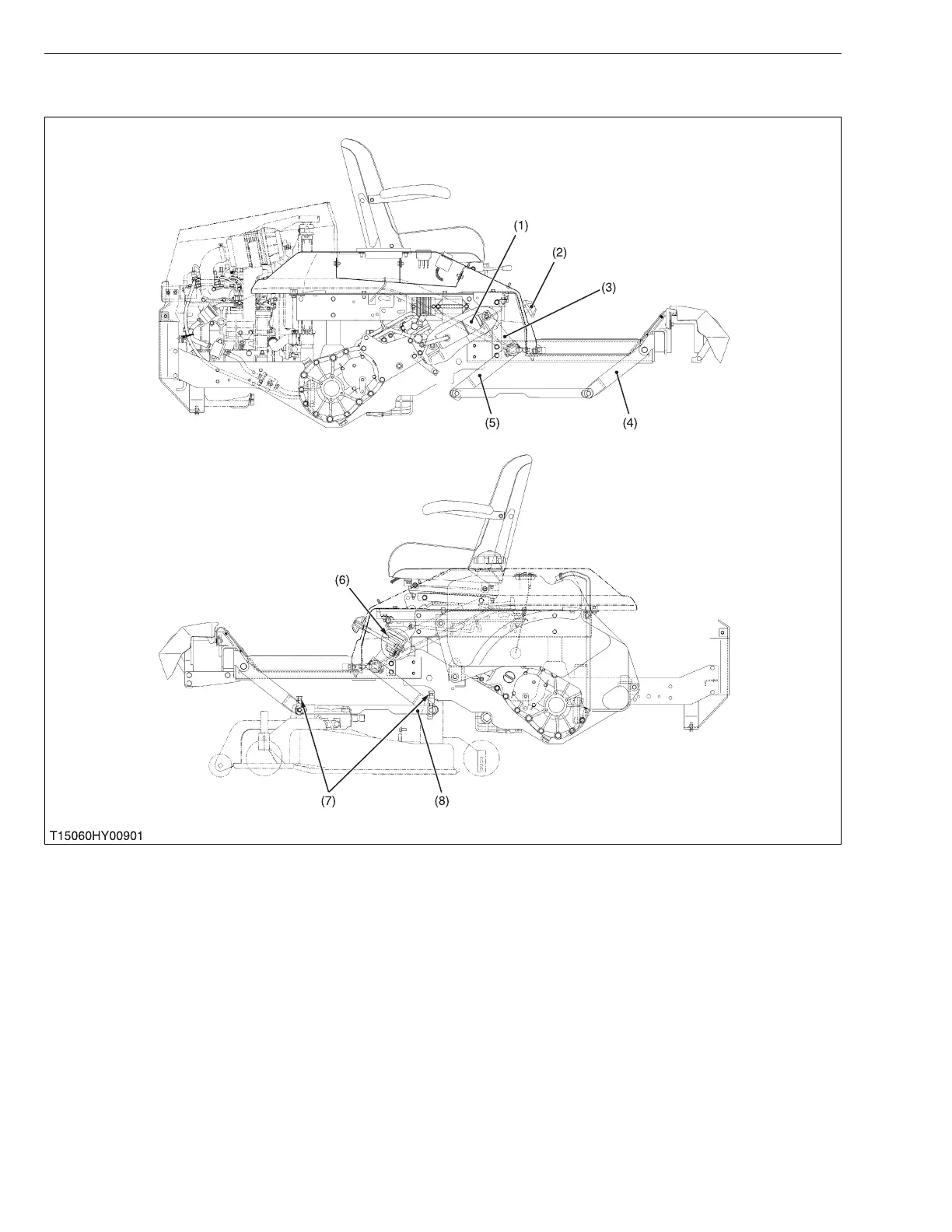
5. MOWER LINKAGE
The lift shaft (3) and rear arm (5) are connected directly with clevice pins.
Front arm (4) and rear arm (5) are linked with horizon plate (8).
As the hydraulic control lever moves to up position, lift cylinder (1) is extended and lift shaft (3) is rotated to pull the
rear arm (5) rearward. As a result, mower is lifted.
The cutting height adjusting dial (2) adjusts cutting height of mower by rotating the adjusting cam (6).
The level of mower deck is adjusted by adjusting the cutting height fine tuning bolt length (7).
(1) Lift Cylinder
(2) Cutting Height Adjusting Dial
(3) Lift Shaft
(4) Front Arm
(5) Rear Arm
(6) Adjusting Cam
(7) Cutting Height Fine Tuning Bolt
(8) Horizon Plate
 Loading...