16. BATTERY/CHARGING SYSTEM
16-5
GRAND DINK 250
CHARGING SYSTEM
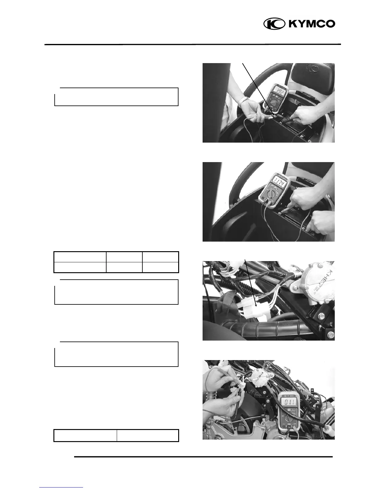
CURRENT TEST
Warm up the engine before taking readings.
Connect an electric tester across the battery
terminals.
Disconnect the red wire from the fuse
terminal and connect an ammeter between the
red wire lead and the fuse terminal.
Attach a tachometer to the engine.
Start the engine and gradually increase the
engine speed to measure the limit voltage and
current.
Limit Voltage/Current: 1415V/0.5A max.
(5000rpm max.)
If the limit voltage is not within the specified
range, check the regulator/rectifier.
PERFORMANCE TEST
Engine Speed 2500rpm 5000rpm
Charging Current 7A min. 9A min.
If the readings do not meet the specified
values, check the regulator/rectifier.
A.C. GENERATOR INSPECTION
Remove the frame center cover.
Disconnect the A.C. generator connector.
Check the continuity between the yellow
wires and ground.
There should be continuity between the
yellow wires and no continuity between each
yellow wire and ground.
Resistance:
YellowYellow 0.61.6Ω
Red Wire
A.C. Generator Connecto
When measuring the charging current,
disconnect the black wire from the
regulator/rectifier wire coupler.
This test can be made without removing
the stator from the engine. Disconnect
the yellow wire from the auto bystarter.
 Loading...