Page 88 - IOM / ROOFTOP BALTIC Series - 0704 - E
CONTROL INTERFACE DC50
CONTROL INTERFACES AND DISPLAYS
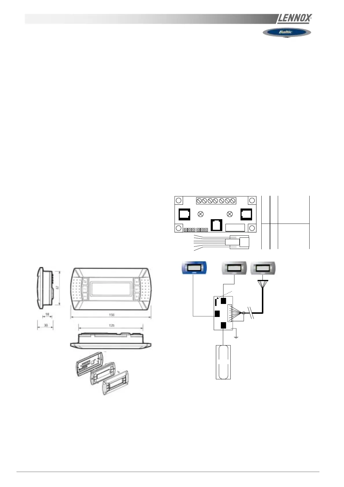
DC50 COMFORT DISPLAY
This is a remote controller for non-technical customer.
This display gives information such as running mode
status of the fan, set point, % of fresh air and outside air
temperature.
It can be used to set or change the scheduling of the
different time zones, the temperature set point, and the %
of fresh air for each zone. It also has the capacity to set a 3
hours override and to force the unoccupied mode for up to
7 days. It displays the real time clock and different faults
signals.
Display
Type FSTN graphic
Back light: Green LEDs
Resolution 120x32 pixels
Power Supply
Voltage from main Climatic board.
Max power: 0.8W
Installation
The DC50 is designed to be mounted on the wall.
* Fit the cable from the DT50 board through the back
piece
* Fasten the back piece to the wall using the rounded
head screws supplied in the packaging
* Connect the cable from the main board on the RJ12
plug on the back of the DC50 display
* Fasten the front panel on the back piece using the
flush head screws supplied
Finally fit the click-on frame
Terminal connection Board installation guide DT50
The board is fitted with three "telephone" RJ12 plugs.
Ensure the board is correctly connected.
Standard connection is:
* Climatic on connector C
* DC50 on connector A
* DS50 on connector B
Jumpers:
"Displays" are supplied directly by the Climatic board with
30Vdc. Take particular care at the path this 30V is taking
when several boards are being used.
J14 and J15 can switch on or off the direct current from the
power supply:
J14 and J15 set between1-2
Connectors A, B, C and screw connector SC are in parallel.
Power supply available to all connectors.
J14 and J15 set between2-3
Connectors B and C are in parallel but line 1 and 6 don't
reach connector A and screw connector SC.
"Displays" connected to these ports will not be powered.
If J14 and J15 are set in different positions the "terminal
connection board" DT50 DOES NOT WORK.
NOTE:
When a shielded wire is used the metallic case of the
"Terminal connection box" DT50 must be earthed.
A
B
C
6
0
BM 50
DS50
DC50
DC50
OR
J14/J15 on 1-2
SC Terminals
RJ12 Pin conn
Description
0 + shield / earth
1 1 +VRL=30V
2 2 GND
3 3 Rx- / Tx-
4 4 Rx+ / Tx+
5 5 GND
6 6 +VRL=30V
1
J 14
DT50
J 15
23
1
2
3
4
5
6
123
06
SC
A
B
C
RJ12 PIN Connection

 Loading...