7
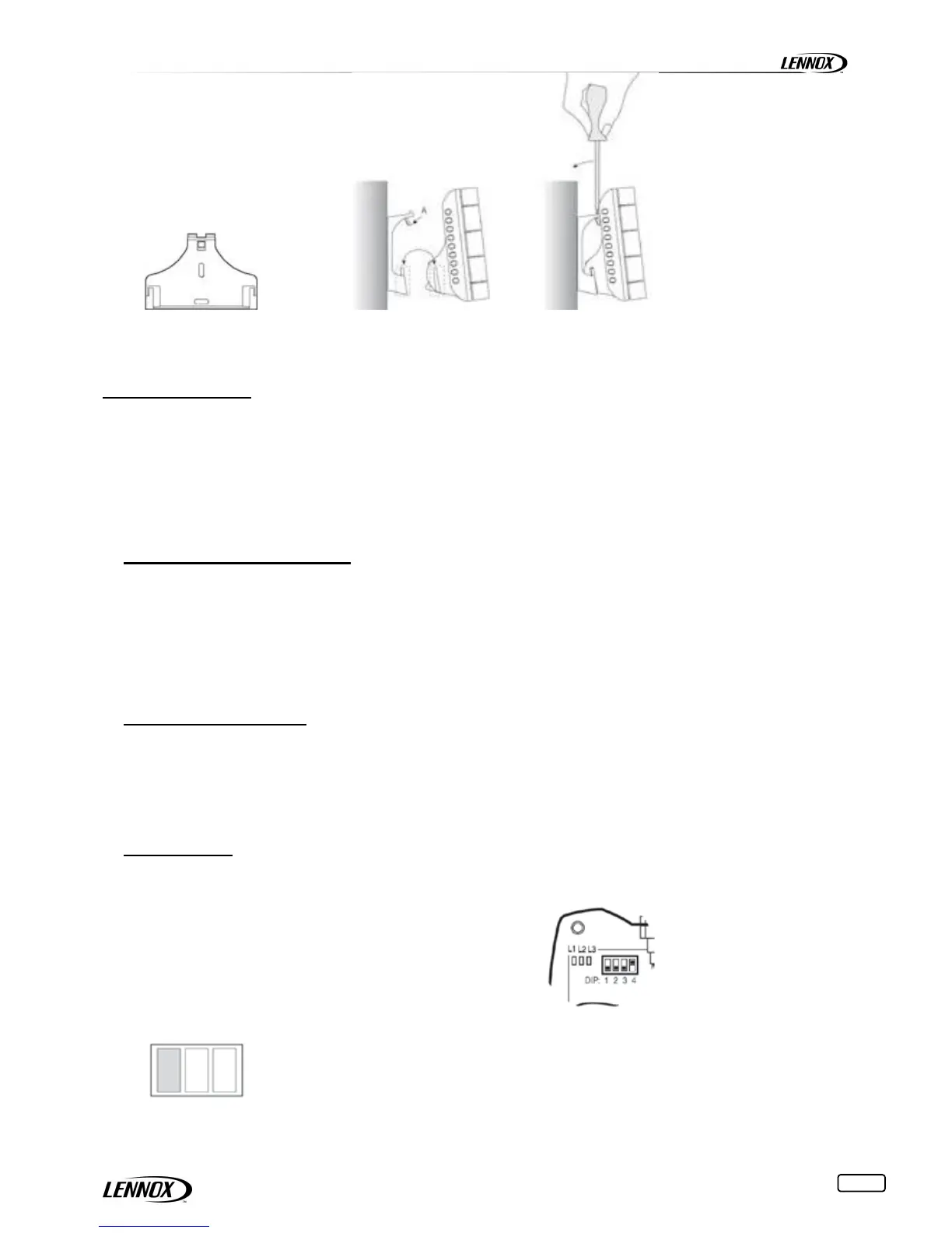
Part A shown in the figure is used to lock the instrument to the support. A screwdriver will be required to remove the
instrument. This plastic part may be essential for hotel-type applications. For applications where the instrument needs to be
removed frequently (residential, office,…) part A can be eliminated simply.
CONFIGURATION
The following chapter describes the procedure for setting the address, configuring and connecting the devices for the
creation of a wireless domain connectable to the Climatic of the unit.
The procedure includes:
1. setting the address of the access point
2. setting the address of the terminals
3. setting the address of the sensors
4. Connecting the modes. In this phase, the terminals and the sensors are associated with the access point.
Visualization with the DS50
The Wireless option must be activated in the program Climatic ™ 50 by 3941 setpoint.
If a DCw must be installed; settle the 3942 setpoint by 1 (0 if not DCw)
The number of SCw installed must be setting in 3943 (between 0 and 6)
All other parameters of the option Wireless are visible on the special screens
To enable these special screens press the button 'Prg' when you're on the menu 000 or menus data 2xxx. Then you
move from one screen to another, press the buttons '↑' or '↓' to see the screen desired.
Setting the addresses
This is a fundamental phase in setting up the system, and allows each device to be identified uniquely.
Important: the address can only be set at this time. Any changes, when the channel has been set (see Automatically
search for wireless communication channel), will be ignored. The address can only be changed after having reinitialised the
device (see Resetting the devices).
Access point
APw
Position the dip-switch in the following manner:
No. 1 to Off
No. 2 to Off
No. 3 to Off
No. 4 to On
This configuration is at No. 8
Power up the access point;
Check that LED L1 (yellow) on the left is always on and the others are off. If the LEDs are not in this
status, reinitialise the access point (see Resetting the devices);
 Loading...