S94P01C -e1
21
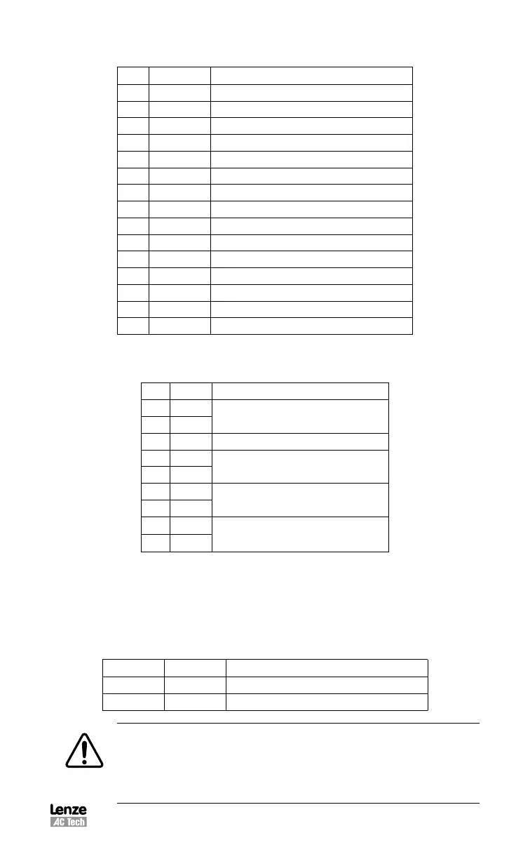
P4A Pin Assignments (Encoder Feedback - E94P Drives)
Pin Name Function
1 EA+ Encoder Channel A+ Input
(1)
2 EA- Encoder Channel A- Input
(1)
3 EB+ Encoder Channel B+ Input
(1)
4 EB- Encoder Channel B- Input
(1)
5 EZ+ Encoder Channel Z+ Input
(1)
6 EZ- Encoder Channel Z- Input
(1)
7 GND Drive Logic Common/Encoder Ground
8 SHLD Shield
9 PWR Encoder supply (+5VDC)
10 HA- Hall Sensor A- Input
(2)
11 HA+ Hall Sensor A+ Input
(2)
12 HB+ Hall Sensor B+ Input
(2)
13 HC+ Hall Sensor C+ Input
(2)
14 HB- Hall Sensor B- Input
(2)
15 HC- Hall Sensor C- Input
(2)
(1)
See Note 1, Section 5.1.7 - Connector and Wiring Notes
(2)
For asynchronous servo motor, an incremental encoder without Hall effect sensors (commutation tracks) can be used.
P4B Pin Assignments (Resolver Feedback - E94R Drives)
Pin Name Function
1 Ref +
Resolver reference connection
2 Ref -
3 N/C
No Connection
4 Cos+
Resolver Cosine connections
5 Cos-
6 Sin+
Resolver Sine connections
7 Sin-
8 PTC+
Motor PTC Temperature Sensor
9 PTC-
5.1.5 P5 - 24 VDC Back-up Power Input
P5 is a 2-pin quick-connect terminal block that can be used with an external 24 VDC
(500mA) power supply to provide “Keep Alive” capability: during a power loss, the
logic and communications will remain active. Applied voltage must be greater than
20VDC.
P5 Pin Assignments (Back-up Power)
Pin Name Function
1 +24 VDC Positive 24 VDC Input
4 Return 24V power supply return
WARNING!
Hazard of unintended operation! The “Keep Alive” circuit will restart the
motor upon restoration of mains power when the enable input remains
asserted. If this action is not desired, then the enable input must be
removed prior to re-application of input power.
 Loading...