S94P01C -e1
24
When using a Lenze motor with resolver feedback and a Lenze resolver cable, the
pins are already configured for operation. If a non-Lenze motor is used, the resolver
connections are made as follows:
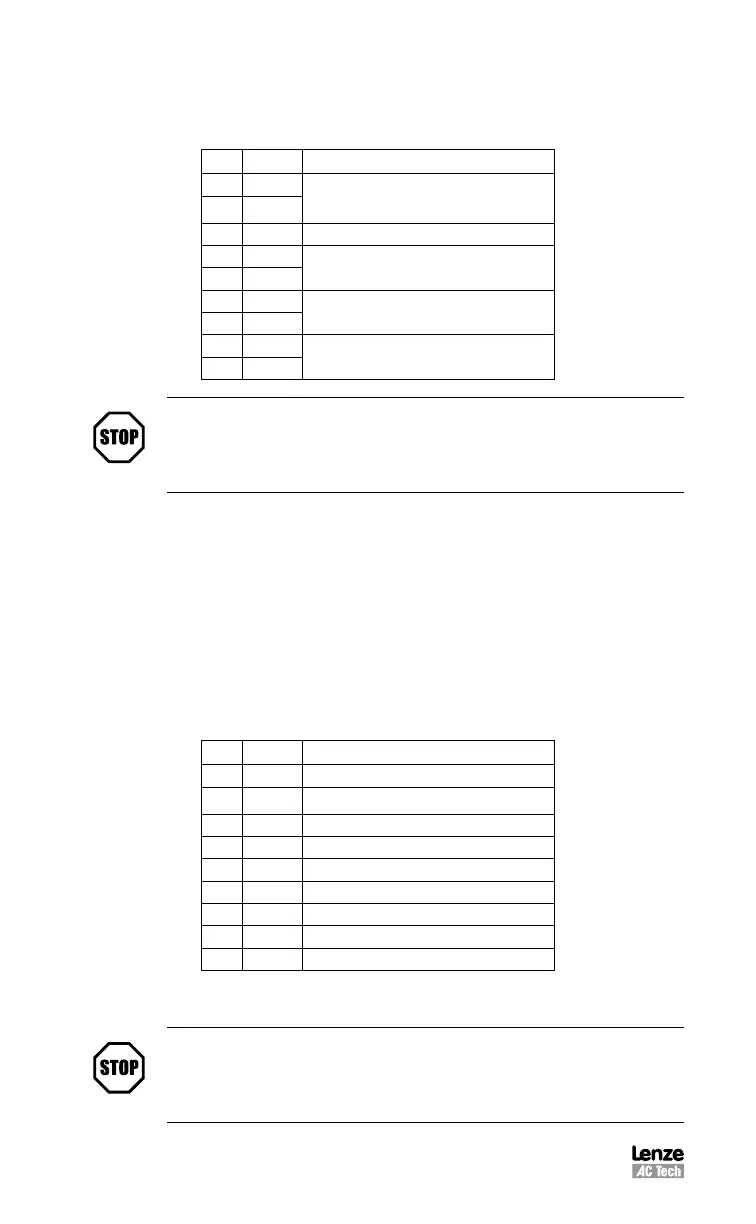
P11 Pin Assignments (Resolver Feedback)
Pin Name Function
1 Ref +
Resolver reference connection
2 Ref -
3 N/C No Connection
4 Cos+
Resolver Cosine connections
5 Cos-
6 Sin+
Resolver Sine connections
7 Sin-
8 PTC+
Motor PTC Temperature Sensor
9 PTC-
STOP!
Use only 10 V (peak to peak) or less resolvers. Use of higher voltage
resolvers may result in feedback failure and damage to the resolver
option module.
5.1.9 P12 - Second Encoder Interface Module (option bay 2)
PositionServo drives can support a second incremental encoder interface for dual-
loop systems. Regardless of what the motor’s primary feedback type is, encoder or
resolver, a 2nd Encoder Option Module, E94ZAENC1, can be installed at Option Bay
2, (P12). Once installed the optional feedback card can be selected as the primary
encoder repeat source from the “Parameter” folder in MotionView. The 2nd Encoder
Option Module includes a 9 pin D-shell male connector. When using a Lenze motor
with encoder feedback and a Lenze encoder cable, the pins are already configured
for operation. If a non-Lenze motor is used, the encoder connections are made as
follows:
P12 Pin Assignments (Second Encoder Feedback)
Pin Name Function
1 E2B+ Second Encoder Channel B+ Input
2 E2A-
Second Encoder Channel A- Input
3 E2A+ Second Encoder Channel A+ Input
4 +5v Supply voltage for Second Encoder
5 COM Supply common
6 E2Z- Second Encoder Channel Z- Input
7 E2Z+ Second Encoder Channel Z+ Input
8 N/C No Connection
9 E2B- Second Encoder Channel B- Input
The second encoder needs to be enabled using MotionView software. See section
“Dual-loop feedback” (Section 8.4) for details.
STOP!
Use only +5 VDC encoders. Do not connect any other type of encoder
to the option module. Otherwise, damage to drive’s circuitry may
result.
 Loading...