S94P01C -e1
31
5.5.2 Motor Over-temperature Protection
If using a motor equipped with an encoder and PTC thermal sensor, the encoder
feedback cable will have flying leads exiting the P4 connector to be wired to the P7.1
(T1) and P7.2 (T2) terminals. If using a motor equipped with a Resolver and a PTC
sensor, the thermal feedback is pased directly to the drive via the resolver 9-pin D
shell connector.
Use parameter “Motor PTC cut-off resistance” (see section 6.3.12) to set the
resistance which corresponds to maximum motor allowed temperature. The parameter
“Motor temperature sensor” must also be set to ENABLE. If the motor doesn’t have
a PTC sensor, set this parameter to DISABLE. This input will also work with N.C.
thermal switches which have only two states; Open or Closed. In this case “Motor PTC
cut-off resistance” parameter can be set to the default value.
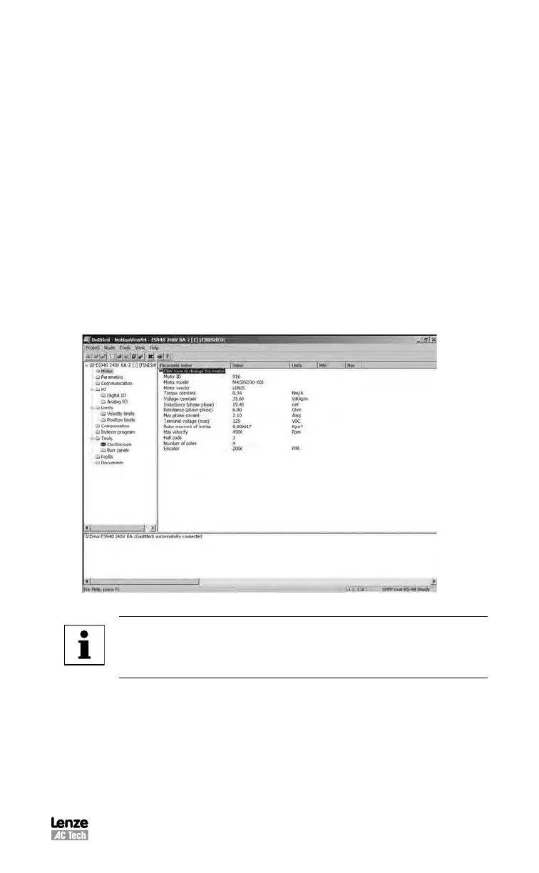
5.5.3 Motor Set-up
Once you are connected to the PostionServo via MotionView a “Parameter Tree”
will appear in the “Parameter Tree Window”. The various parameters of the drive are
shown here as folders and files. If the “Motor” folder is selected, all motor parameters
can be viewed in the “Parameter View Window”. To view selected motor parameters
or to select a new motor click the section marked “CLICK HERE TO CHANGE”.
S911
MotionView’s “Motor Group” folder and its contents
Note
If the drive is ENABLED, a new motor cannot be set. You can only set
a new motor when the drive is DISABLED.
 Loading...