S94P01C -e1
25
5.2 Digital I/O Details
5.2.1 Step & Direction / Master Encoder Inputs (P3, pins 1-4)
You can connect a master encoder with quadrature outputs or a step and direction pair
of signals to control position in step / direction operating mode (stepper motor emulation).
These inputs are optically isolated from the rest of the drive circuits and from each other.
Both inputs can operate from any voltage source in the range of 5 to 24 VDC and do not
require additional series resistors for normal operation.
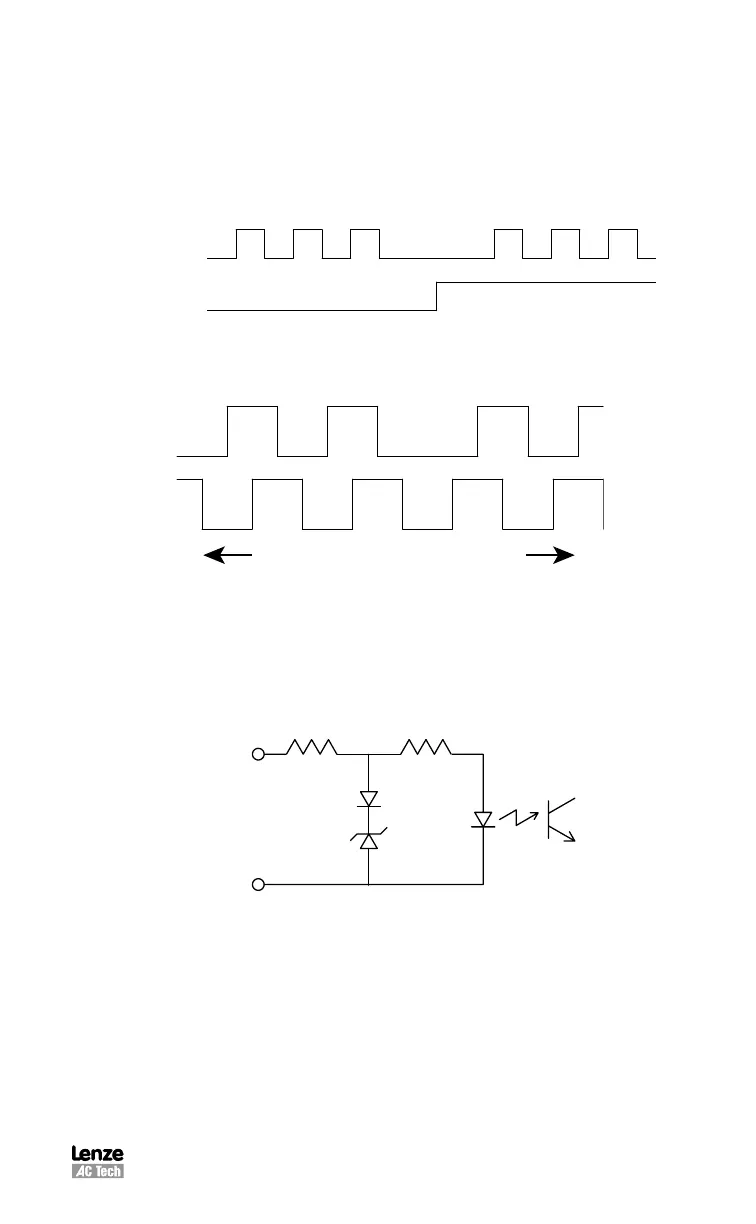
S904
Timing characteristics for Step And Direction signals
S905
Timing characteristics for Master Encoder signals
Input type/ output compatibility Insulated, compatible with Single-ended or
differential outputs (5-24 VDC)
Max frequency (per input) 2 MHz
Min pulse width (negative or positive) 500nS
Input impedance 700 Ω (approx)
B6 $HI:E
B7 $9>G
B6"$HI:E"
B7"$9>G"
+%%7 &%%7
*#+K
S906
Master encoder/step and direction input circuit
Differential signal inputs are preferred when using Step and Direction. Single ended
inputs can be used but are not recommended. Sinking or sourcing outputs may also
be connected to these inputs. The function of these inputs “Master Encoder” or “Step
and Direction” is software selectable. Use MotionView set up program to choose
desirable function.
 Loading...