from Firmware V06.00 - DMS 1.1 EN - 11/2011 L 11
8400 StateLine C | Operating instructions
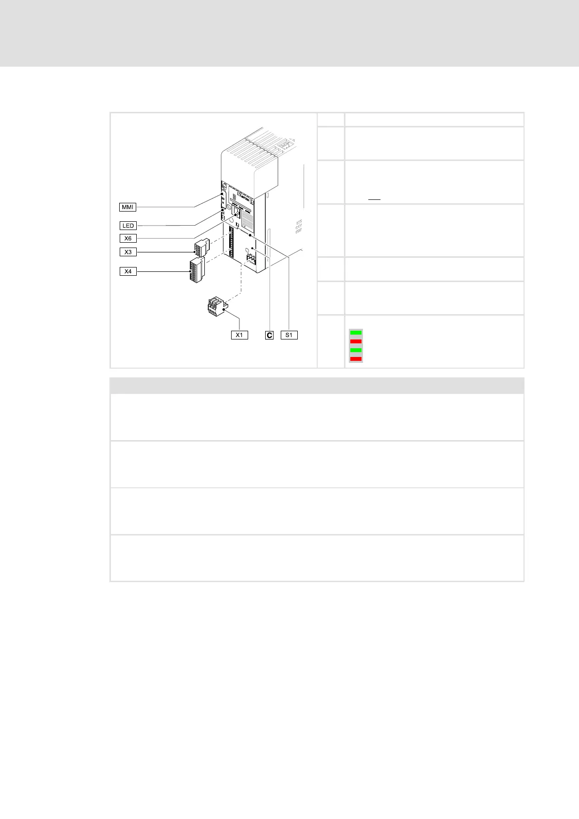
Overview of terminals
Control terminals
X1 CANopen connection
S1 CANopen settings
(Bus terminating resistor, baud rate and node
address)
X3 • Analog inputs/outputs
• 10 V reference voltage
Note: Voltage input A1U and current input A1I
must not
be used simultaneously!
X4 • Digital inputs/outputs
(according to IEC 61131-2, type 1)
• External 24 V supply voltage
(for control electronics)
• 24 V voltage output
X6 Diagnostic interface (DIAG)
• For keypad ( 15) or PC connection ( 19)
MMI Slot for memory module ( 20)
• MMI = abbreviation for "Memory Module
Interface"
LED Status displays of the device status ( 45)
Description of the warning signs
Long discharge time!
All power terminals remain live for some minutes after mains disconnection!
The time is given below the warning symbol on the device.
High leakage current!
Carry out fixed installation and PE connection in accordance with EN 61800-5-1!
Electrostatic sensitive devices!
Before working on the device, the staff must ensure to be free of electrostatic charge!
Hot surface!
Risk of burns!
Hot surfaces should not be touched without wearing protective gloves.
'595'<
&$1581
'59(55
&$1(55

 Loading...
