Installation
Electrical installation
Wiring with a host (master)
5
l
24
EDSMF2133IB EN 5.0
5.2.2 Wiring with a host (master)
{ Danger!
You have to provide additional electrical isolation if ...
ƒ an 820X and 821X controller is connected to the host and
ƒ a safe electrical isolation (reinforced insulation) according to EN 61800−5−1
is required.
Basic wiring of the PROFIBUS
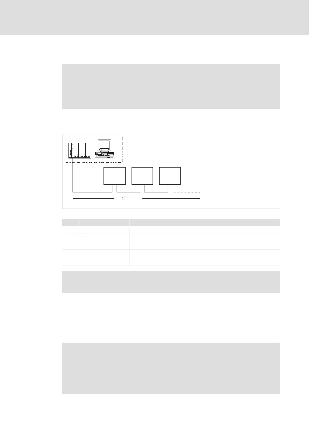
The connection of the PROFIBUS bus system is shown in the general layout drawing.
333
1
222
0m
1200 m
GG + 2133 GG + 2133 GG + 2133
E82ZAFP005
Fig. 5−2 Example: PROFIBUS with RS485 wiring (without repeater)
No. Element Comment
1 Host e.g. PC or PLC with PROFIBUS master interface module
2 Bus cable Connects the PROFIBUS master interface module to the communication
modules.
l The baud rate depends on the bus cable length (^ 26).
3 PROFIBUS slave Applicable standard device (GG, ^ 12) with communication module
l Activate the bus terminating resistors on the first and last physical bus
device (^ 24).
) Note!
When using a repeater, max. 125 devices can communicate via the PROFIBUS.
Bus terminating resistor
The PROFIBUS must be terminated by a bus terminating resistor at the physically first and
last station.
The bus terminating resistor is in the bus connector (¶ 128)and is activated using a
switch.
) Note!
ƒ If you want to disconnect individual bus devices, ensure that the bus
terminators at the cable ends remain active.
ƒ Please note that the bus termination is no longer active if ...
– the connector has been disconnected e.g. in service case;
– the voltage supply of the communication module has been switched off.

 Loading...


