Process data transfer
Lenze device control
Process data signal for 9300 servo inverters
7
l
57
EDSMF2133IB EN 5.0
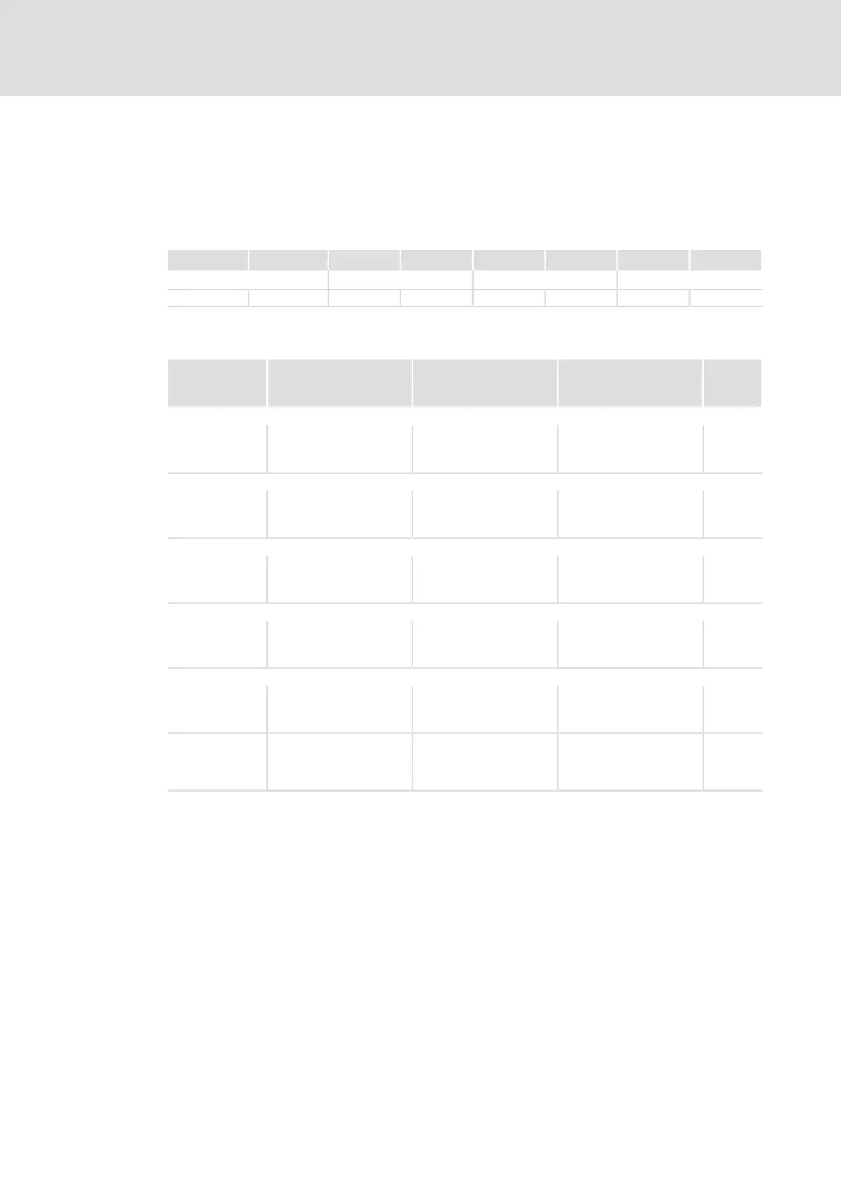
7.1.4 Process data signal for 9300 servo inverters
The assignment of the process data for the 93XX controller can be changed by configuring
the system blocks AIF−IN and AIF−OUT.
Process data telegram from drive
Byte 1 Byte 2 Byte 3 Byte 4 Byte 5 Byte 6 Byte 7 Byte 8
DRIVECOM status word AIF−OUT.W1 AIF−OUT.W2 AIF−OUT.W3
High byte Low byte High byte Low byte High byte Low byte High byte Low byte
Assignment of AIF−OUT.W1 ... W3 depending on the signal configuration selected under
C0005:
Signal
configuration
(C0005)
AIF−OUT.W1 AIF−OUT.W2 AIF−OUT.W3 AIF−OUT.
D1
Speed control
1003
1013
1113
MCTRL−NACT
Actual speed value
100%= 16383
MCTRL−MSET2
Torque display
100%= 16383
MCTRL−NSET2
Speed controller input
100%= 16383
Not used
Torque control
4003
4013
4113
MCTRL−MSET2
Torque display
100%= 16383
MCTRL−NACT
Actual speed in %
100%= 16383
MCTRL−NSET2
Speed controller input
100%= 16383
Not used
LF master
5003
5013
5113
MCTRL−NACT
Actual speed value
100%= 16383
MCTRL−MSET2
Torque display
100%= 16383
MCTRL−NSET2
Speed controller input
100%= 16383
Not used
LF slave rail
6003
6013
6113
MCTRL−NACT
Actual speed value
100%= 16383
MCTRL−PHI−ACT
Angle actual value
MCTRL−MSET2
Torque setpoint in %
100%= 16383
Not used
LF slave cascade
7003
7013
7113
MCTRL−NACT
Actual speed value
100%= 16383
MCTRL−PHI−ACT
Angle actual value
MCTRL−MSET2
Torque setpoint in %
100%= 16383
Not used
Not equal to
xxx3
(except for own
configurations)
MCTRL−NACT
Actual speed value
100%= 16383
MCTRL−MSET2
Torque display
100%= 16383
MCTRL−PHI−ACT
Angle actual value
Not used
In the controller, the signals AIF−OUT.W1 ... W3 can be assigned to other signals. For this,
the system block configuration is used. The AIF−OUT system block defines the output data
of the controller as data interface to the communication module.
Detailed information on system block configuration, 93XX signal configurations (main
configurations 1000, 4000, 5000 etc.) and the AIF−OUT system block can be found in the
documentation of the 93XX controller.

 Loading...


