EasyManua.ls Logo

LG 55UK6500AUA Service Manual

LG 55UK6500AUA
97 pages
To Next Page IconTo Next Page
To Previous Page IconTo Previous Page
Page #3 background imageLoading...
Page #3 background image
- 3 -
Copyright © LG Electronics Inc. All rights reserved.
Only for training and service purposes.
Many electrical and mechanical parts in this chassis have special safety-related characteristics. These parts are identified by in the
Exploded View.
It is essential that these special safety parts should be replaced with the same components as recommended in this manual to prevent
Shock, Fire, or other Hazards.
Do not modify the original design without permission of manufacturer.
General Guidance
An isolation Transformer should always be used during the
servicing of a receiver whose chassis is not isolated from the AC
power line. Use a transformer of adequate power rating as this
protects the technician from accidents resulting in personal injury
from electrical shocks.
It will also protect the receiver and it's components from being
damaged by accidental shorts of the circuitry that may be
inadvertently introduced during the service operation.
If any fuse (or Fusible Resistor) in this TV receiver is blown,
replace it with the specified.
When replacing a high wattage resistor (Oxide Metal Film Resistor,
over 1 W), keep the resistor 10 mm away from PCB.
Keep wires away from high voltage or high temperature parts.
Before returning the receiver to the customer,
always perform an AC leakage current check on the exposed
metallic parts of the cabinet, such as antennas, terminals, etc., to
be sure the set is safe to operate without damage of electrical
shock.
Leakage Current Cold Check(Antenna Cold Check)
With the instrument AC plug removed from AC source, connect an
electrical jumper across the two AC plug prongs. Place the AC
switch in the on position, connect one lead of ohm-meter to the AC
plug prongs tied together and touch other ohm-meter lead in turn to
each exposed metallic parts such as antenna terminals, phone
jacks, etc.
If the exposed metallic part has a return path to the chassis, the
measured resistance should be between 1 MΩ and 5.2 MΩ.
When the exposed metal has no return path to the chassis the
reading must be infinite.
An other abnormality exists that must be corrected before the
receiver is returned to the customer.
Leakage Current Hot Check (See below Figure)
Plug the AC cord directly into the AC outlet.
Do not use a line Isolation Transformer during this check.
Connect 1.5 K / 10 watt resistor in parallel with a 0.15 uF capacitor
between a known good earth ground (Water Pipe, Conduit, etc.)
and the exposed metallic parts.
Measure the AC voltage across the resistor using AC voltmeter
with 1000 ohms/volt or more sensitivity.
Reverse plug the AC cord into the AC outlet and repeat AC voltage
measurements for each exposed metallic part. Any voltage
measured must not exceed 0.75 volt RMS which is corresponds to
0.5 mA.
In case any measurement is out of the limits specified, there is
possibility of shock hazard and the set must be checked and
repaired before it is returned to the customer.
Leakage Current Hot Check circuit
IMPORTANT SAFETY NOTICE
SAFETY PRECAUTIONS

Table of Contents

Other manuals for LG 55UK6500AUA

Question and Answer IconNeed help?

Do you have a question about the LG 55UK6500AUA and is the answer not in the manual?

LG 55UK6500AUA Specifications

General IconGeneral
Screen Size55 inches
Display TypeLED
Smart TVYes
HDMI Ports4
USB Ports2
Audio Output Power20W
Refresh Rate60Hz
Wi-FiYes
Speaker System2.0 Channel
ProcessorQuad Core Processor
BluetoothYes
Resolution3840 x 2160
HDRYes (HDR10, HLG)

Summary

Safety Precautions and Guidelines

General Safety Guidance

General safety procedures for servicing, including using isolation transformers and handling fuses.

AC Leakage Current Checks

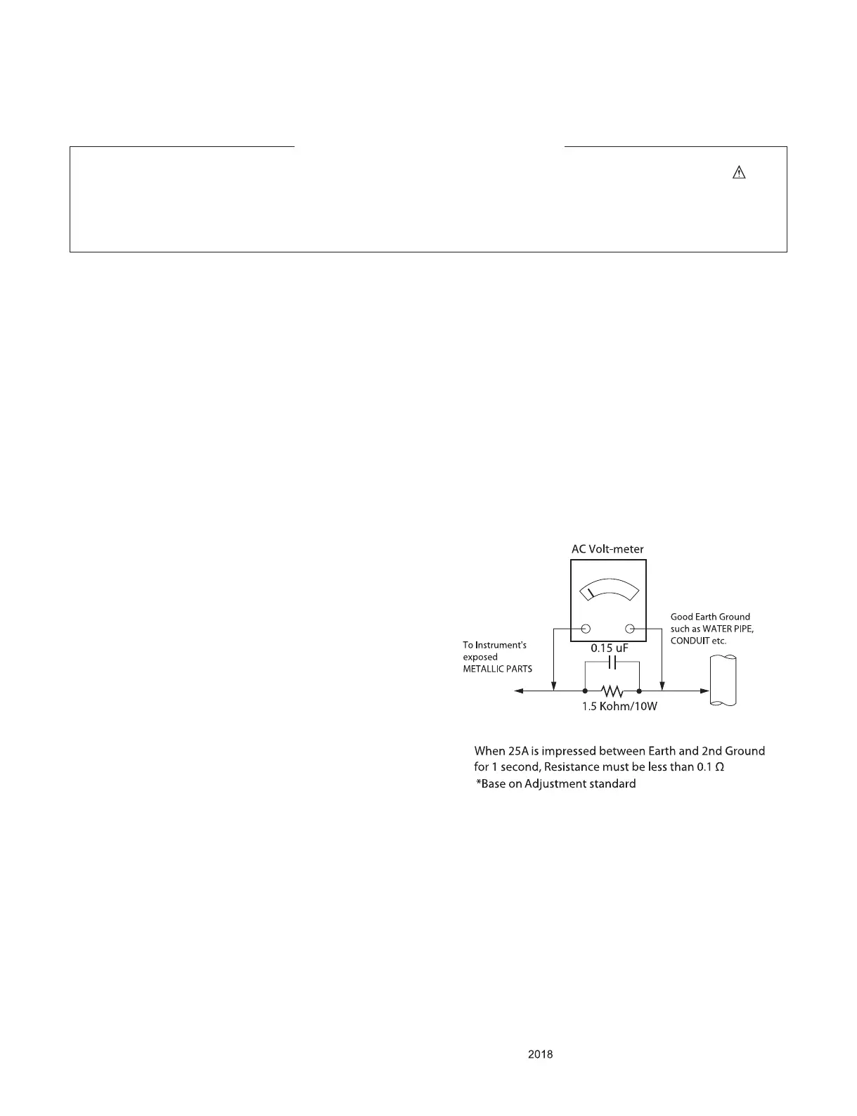
Procedures for performing AC leakage current checks (cold and hot) to ensure safety.

Servicing Precautions and Procedures

General Servicing Procedures

Essential procedures for safe and effective servicing of the TV, including handling components and tools.

Handling Electrostatic Sensitive Devices

Guidelines for safely handling components sensitive to static electricity to prevent damage.

Soldering Techniques and Guidelines

Best practices for soldering, including temperature, solder type, and tip maintenance.

Component Replacement and Repair

IC, Transistor, and Diode Replacement

Step-by-step guides for replacing integrated circuits, transistors, and diodes.

Fuse, Resistor, and Foil Repair

Procedures for replacing fuses and resistors, and repairing damaged circuit board foil.

Television Specifications

General System Specifications

Details on market, broadcasting systems, channel support, and input/output interfaces.

External Input Support Formats

Component Input Formats

Supported signal formats for Component (Y, PB, PR) inputs, including resolution and timing.

HDMI Input Formats

Supported signal formats for HDMI inputs (PC/DTV), including resolution and timing.

Software Update Procedures

USB Software Update

Instructions for updating the TV's software using a USB drive.

Network Software Update (NSU)

Instructions for updating the TV's software over a network connection.

System Architecture and Block Diagrams

Main IC and Panel Interface

Diagram of the main IC and its interface with panel technologies like EPI and CEDS.

Input/Output Interfaces

Diagrams detailing video, audio, HDMI, USB, Wi-Fi, and tuner interfaces.

Communication and Control Maps

Maps illustrating I2C bus and GPIO pin assignments for system control.

Power Management and Distribution

Power Supply Voltage Specifications

Specifies key voltage rails and test points for power supply diagnostics.

External View and Component Identification

Exploded View of the Television Set

Visual diagram showing the physical layout and assembly of the TV set.

Disassembly and Reassembly Procedures

Initial Screw Disassembly

Step-by-step guide for disassembling the TV by removing specific screws.

Troubleshooting Methodology

Video Error Diagnostics

Procedures for diagnosing and resolving video-related problems like no video, picture distortion, or freezing.

Power Error Diagnostics

Steps to troubleshoot power-related faults, including no power and intermittent operation.

Audio Error Diagnostics

Diagnostic flowcharts for resolving audio problems such as no sound or distorted audio.

Function Error Diagnostics

Troubleshooting guides for functional errors like remote control, Wi-Fi, and device connectivity issues.

Noise and Exterior Defect Resolution

Methods for diagnosing and fixing noise issues and external physical defects on the TV.

Power Board Diagnostic and Testing

General Power Board Voltage Checks

Procedures for checking power board voltages and sequences on the main power board.

Model-Specific Power Board Diagnostics

Detailed diagnostic methods for different power board models using specialized JIGs and tests.

Related product manuals