3. Product Overview DVI-OPT-220-Pro series – User's Manual 12
Electrical Connections
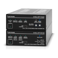
DVI-OPT220-Pro series devices transmit the video signal via multimode
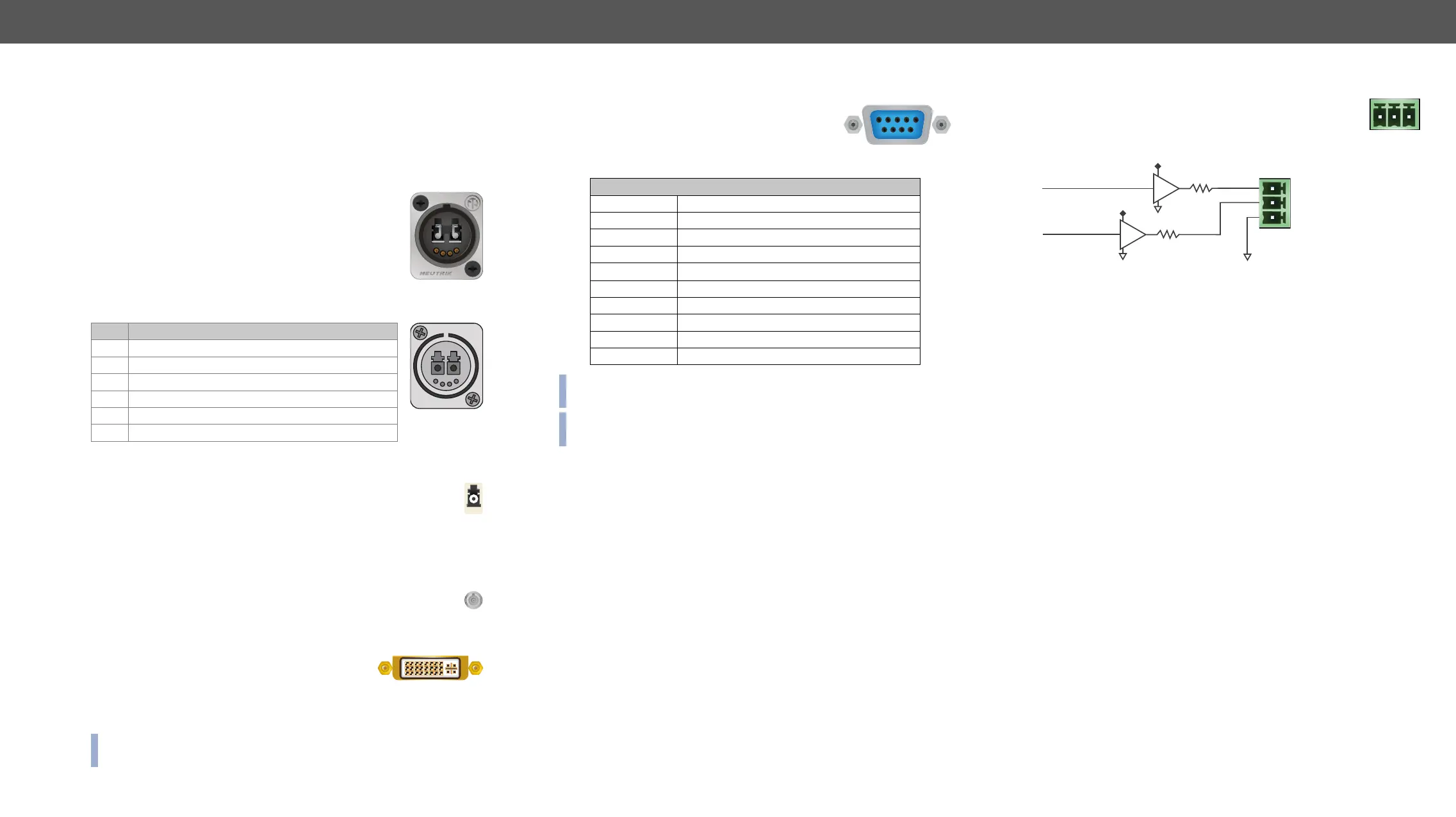
Neutrik OpticalCON Duo Connector
DVI-OPT-RX220-Pro and DVI-OPT-TX220-Pro models
have
channels, channel A and channel B. Only one channel
is used (from channel A on the transmitter to channel B
on the receiver). Neutrik opticalCON DUO is compatible
with 2x LC connector.
Pin Assignment of Neutrik OpticalCON Duo Connector
Pin Signal
1 GND
2 Remote power for receiver DC out +15V
3 Remote power for receiver DC out +15V
4 GND
A Channel A
B Channel B
LC Connector
One channel of the Neutrik connector is not used by the extenders
for signal transmission and it is internally connected to the LC
break-out connector. For more information about break-out
connector see Application Example of Break-out Connector
section.
SC Connector
DVI-OPT-RX220-ST-Pro and DVI-OPT-TX220-ST-Pro models
supplied with ST optical connectors.
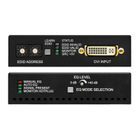
DVI Inputs and Outputs
29-pole DVI-I connectors, however only digital
pins are internally connected. This way, user can
plug in any DVI connector, but keep in mind that
analog signals (such as VGA or RGBHV) are NOT
processed.
INFO: Always use high quality DVI cable for connecting sources and
displays!
B
A
1
4
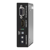
RS-232 Control Port
Devices can be remote controlled through
industry standard 9-pin D-SUB female connector
located on the rear panel of the unit. Please use a
standard RS-232 Male to Female cable (straight
through).
D-sub connector pin assignment for standard RS-232
Pin nr. Pinout
1 NC - non-connected
2
3
4 DTR (Internally connected to Pin 6)
5
6 DSR (Internally connected to Pin 4)
7 RTS (Internally connected to Pin 8)
8 CTS (Internally connected to Pin 7)
9 NC - non-connected
INFO: DVI-OPT-220-Pro extenders are DCE unit according to its pin-out.
For more information see Serial Management section.
INFO: Factory default settings are the same in the transmitter and
receiver: 9600 Baud, 8 data bit, 1 stop bit, no parity.
TTL outputs can be used to give a signal to any third-party
device. Separate signals indicate the detected laser and
the presence of the received DVI signal.
Alarm Outputs
DVI Detect: Indicates when a valid DVI clock signal is extracted
is detected. Logic 0 (GND) means that a valid DVI signal cannot be
extracted from the optical signal.
Laser Detect: Indicates when a laser beam is detected at the Neutrik
connector. Logic 1 (+5V) means that a laser beam with the appropriate
wavelength is detected. Logic 0 (GND) means that either there is no
laser signal or its level is too low to be recognized.
GND: Ground reference signal for alarm outputs. Connected to chassis
ground.
Compatible Plug Type
Phoenix
®
Laser detect
Pin 1: DVI detect (+5V)
Pin 2: Laser detect (+5V)
Pin 3: GRD
+5V
300Ω
300Ω
 Loading...