3. Product Overview DVI-OPT-220-Pro series – User's Manual 13
For more details about the supported cable extension see Maximum Extension Distances section.
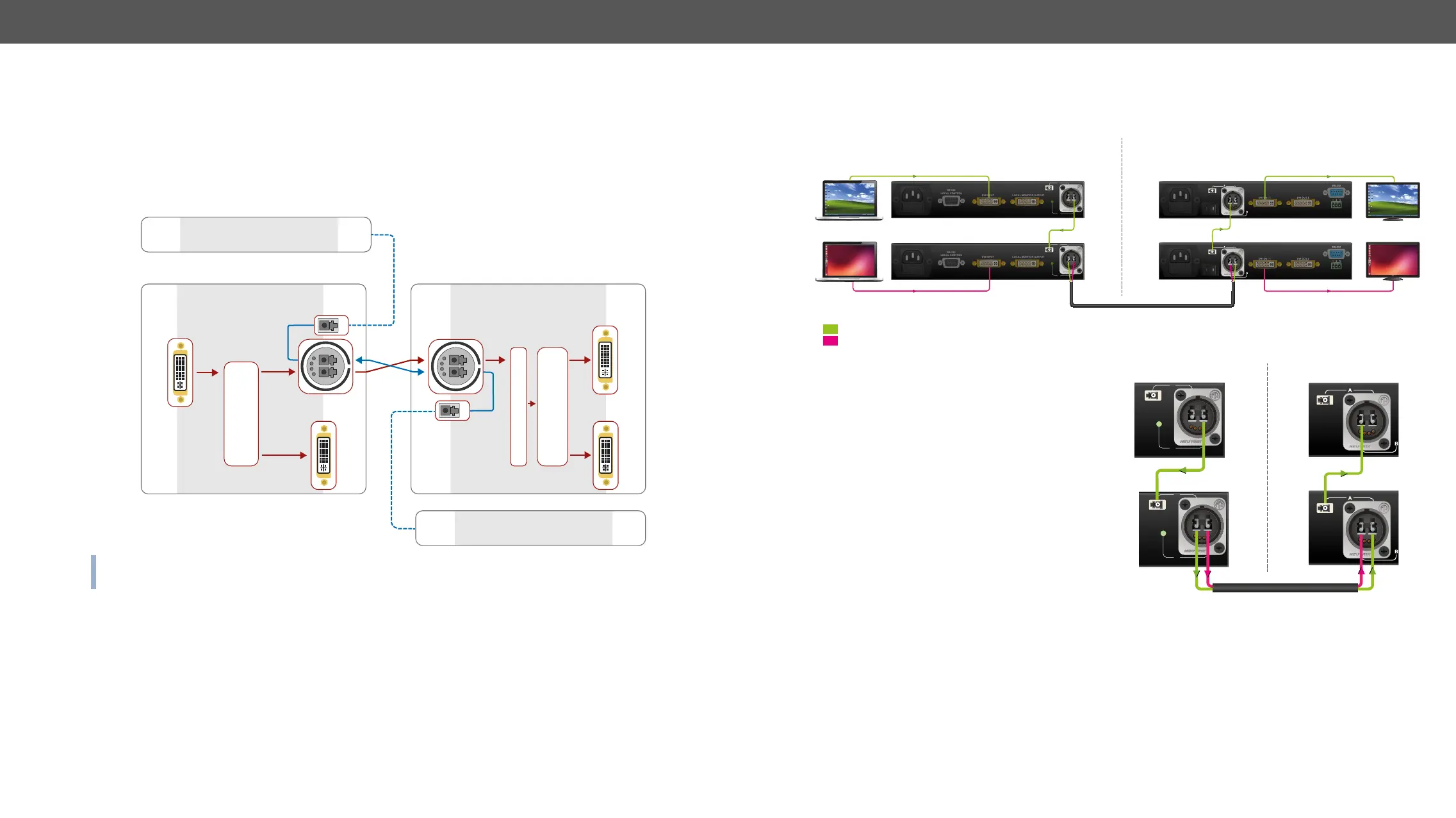
Port Diagram of Optical Interface
A and channel B. Since Lightware
INFO: Red line shows the main direction of the video signal. The blue line represents the optical signal via
B
A
DVI-D
IN
DVI-D
OUT
DVI-D
OUT 1.
DVI-D
OUT 2.
B
A
A
B
Break-out
connector
Break-out
connector
Neutrik
connector
DVI-OPT-RX220-Pro
DVI-OPT-TX220-Pro
Other ber device
Other ber device
Neutrik
connector
DVI
Splitter
Reclocker
DVI
Splitter
Application Example of Break-out Connector
receiver pair with only one Neutrik opticalCON DUO cable. See the application example below.
Channel A. Channel B is directly connected to the
the unit. Any optical signal can be transferred through
this channel in any direction.
Channel B. Channel A is directly connected to the
the unit. Any optical signal can be transferred through
this channel in any direction.
A
B
A
B
LC-LC fiber
optical cable
LC-LC fiber
optical cable
Neutrik opticalCON up to 2500m
Source 1. Sink 1.
Sink 2.
Source 2.
A/V Signal 1.
A/V Signal 2.
DVI
DVI
DVI
DVI
Transmitter side
Receiver side
A
B
A
B
A
LC-LC fiber
optical cable
LC-LC fiber
optical cable
Neutrik opticalCON up to 2500m
Transmitter side Receiver side
 Loading...