Rev: 10.22.19 Page 13
CCD-0001541
Wiring the System
1. Connect 12V DC and ground from the unit's power supply to the motor's location with 10 AWG (2.59
mm) stranded electrical wire.
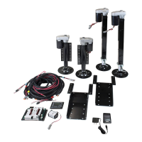
2. Connect a 12V DC line to the solid white wire of the supplied power pigtail and the ground wire to the
black striped wire of the pigtail (Fig. 22).
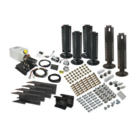
3. Run the RJ-11 COMM cable from the bed lift control switch to the control module.
NOTE: When holding the locking tabs toward you (Fig. 23), the wire colors are the same left-to-right.
Chassis Ground
+12V DC
Fig. 22
Fig. 23
4. Plug the power pigtail, COMM cable, PnP motor, PnP brake, the 3-pin upper PnP microswitch and the
2-pin lower PnP microswitch into the PnP control module. See Wiring Diagram (Fig. 27).
5. Secure the control module to the unit using the module's two mounting holes.
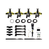
6. Use a router or 1 1/2" (38 mm) hole saw to create an opening in the wall or cabinet panel where the
control switch is to be mounted.
A. Run the COMM cable through the opening (Fig. 24).
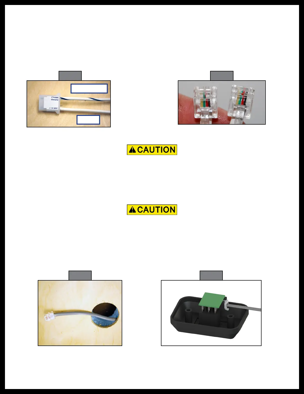
Fig. 24 Fig. 25
Make sure the printed circuit board is not in contact with any metallic surface or object.
Metal-to-metal contact between the circuit board and any other metallic surface can damage
(short-circuit) the control switch. A short-circuit may cause the bed lift to operate without pressing
the switch, which could cause personal injury or component damage.
Leave a small downward loop in the COMM cable to reduce the risk of moisture or condensation
running down the cable into the PnP module.
B. Plug the COMM cable into the connector under the printed circuit board located on the back of
the control switch (Fig. 25).
 Loading...