Rev: 10.22.19 Page 14
CCD-0001541
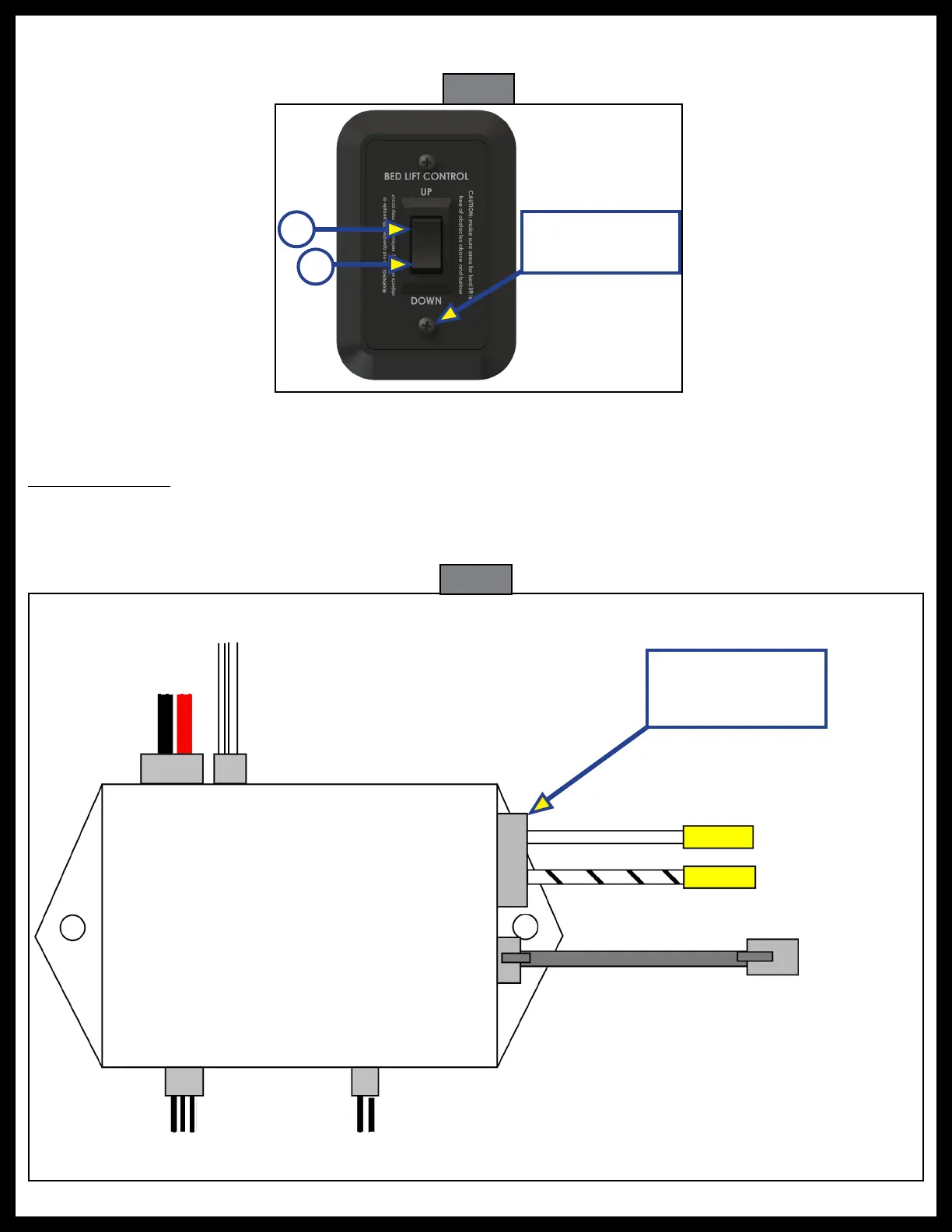
7. Place the BED LIFT CONTROL switch (Fig. 26) over the hole and secure it with the screws provided.
Make sure the switch is positioned such that both screws will securely hold the switch in place.
Fig. 26
Butt
Connectors
+12V DC
Ground
}
10 AWG
(2.59 mm)
stranded
electrical wire
from power
source
RJ-11 Communication
Cable
RELAY CONTROL MODULE
(Top View)
3-pin 2-pin
Power Pigtail
supplied with Relay
Control Module
NOTE: RJ-11 cable must be straight
through cable — standard
telephone cable will not work.
Fig. 27
B
A
Switch Mounting
Screws
To
Brake
To
Motor
To Upper
Limit Switch
To Lower
Limit Switch
Relay Control Module
All outputs are marked on underside of the relay control module (Fig. 27).
Wiring Diagram
RVIA wiring requirements restrict the length of exposed motor leads to a maximum of 10" (254 mm).
Therefore, the Relay Control Module must be placed above the motor or on the wall of the unit in close
enough proximity to the motor that the 10" (254 mm) motor lead will reach.
 Loading...