Rev: 10.22.19 Page 4
CCD-0001541
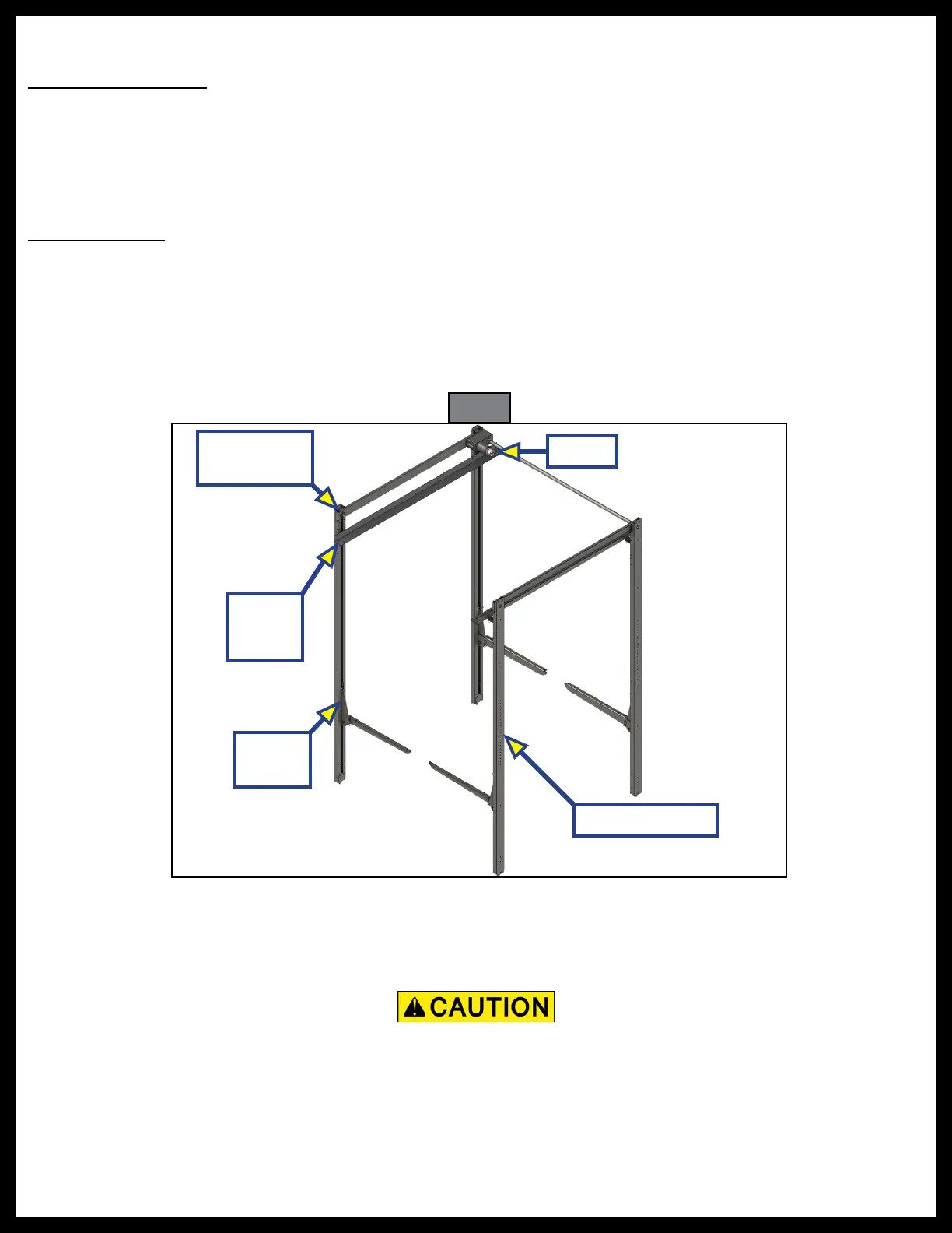
Fig. 1
Lower
Trolley
Preparation
Resources Required
• One to two people, depending on task
•
⁄
" Allen wrench
• Phillips screwdriver
• Tape measure
•
¼
" Wood or self-tapping sheet metal screws (OEM-supplied)
Pre-installation
1. The bed lift frame (Fig. 1) must be installed squarely at the same height side-to-side and at the same
distance from front-to-back in the unit, with vertical rails parallel side-to-side. Leave wooden packing
strips in place until system is secured to the unit.
2. Sufficient backing, a minimum of 1/8" (3 mm) aluminum tube or wood, must be incorporated within the
walls of the unit to support the load of the bed lift with bed platforms installed. The bed lift is rated at
600 lbs (272 kg) per platform attachment (static load).
Installation
1. Use 1/4" (6 mm) wood or self-tapping sheet metal screws (OEM-supplied) of sufficient length to safely
secure the C-channel vertical rails to hold 600 lbs (272 kg) per platform attachment (static load).
NOTE: Screws MUST NOT interfere with any moving parts of the bed lift system.
NOTE: The number of mounting holes will vary according to the vertical rail length of the system being installed.
NOTE: Use the smaller holes for alternate mounting locations of the upper bunk stop.
C-channel Rails
Upper
Trolley
Manual
Crank Point
A pinched travel limit microswitch wire can cause damage to the bed lift system. Make sure installed
lower vertical rail mounting screws do not pinch, cut or crush the lower limit switch wire. Also make
sure the upper limit switch wire is not pinched behind the motor mounting plate or rubbing against the
chain or sprocket assembly.
Motor
 Loading...