Rev: 10.22.19 Page 15
CCD-0001541
Testing the System
Trolley Travel
This test requires two people. Each time the micro-limit switch is depressed the drive trolley should stop.
If the trolley fails to stop when the switch is depressed, re-check all electrical connections and 12V DC and
ground wire connections.
1. Press and hold the control switch UP button (Fig. 26A) to make sure that the trolleys travel upward.
If the trolleys travel downward, check the orientation of the 12V DC and ground connections to the
power pigtail (Fig. 22). Refer to Wiring Diagram (Fig. 27).
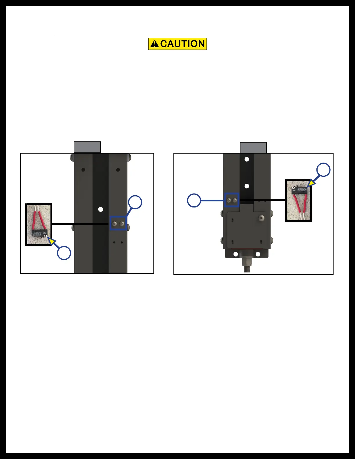
NOTE: The limit switches (microswitches) (Figs. 28A and 29A) are located behind the two small Phillips
head screws (Figs. 28B and 29B) near the top and bottom of the vertical rail below the motor.
Fig. 28
B
A
Moving parts can cut or crush. Keep clear of moving parts.
2. While running the system upward, toggle the upper microswitch with a stiff wire or large paper clip (Fig. 28A).
3. Press and hold the control switch DOWN button (Fig. 26B) to make sure that the trolleys travel
downward. If the trolleys travel upward, check the orientation of the 12V DC and ground connections
to the power pigtail (Fig. 22). Refer to Wiring Diagram (Fig. 27).
4. While running the system downward, toggle the lower microswitch with a stiff wire or large paper
clip (Fig. 26A).
5. If the system fails to operate, check all electrical connections.
A
Fig. 29
B
 Loading...