Description
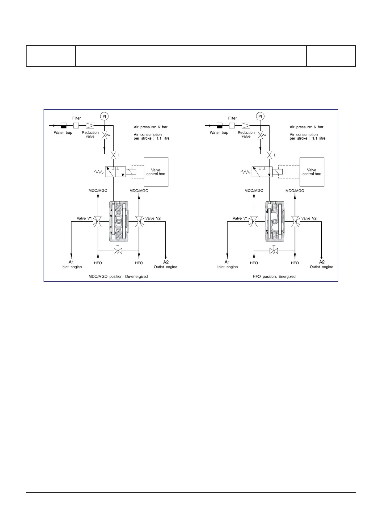
Figure 1: Pneumatic diagram for 3-way changing valves V1 & V2.
The fuel change-over system consists of two
remote controlled and interconnected 3-way valves,
which are installed immediately before each Gen-
Set. The 3-way valves “V1-V2” are operated by an
electrica/pneumatic actuator of the simplex type,
with spring return and a common valve control box
for all GenSets.
The flexibility of the system makes it possible, if
necessary, to operate the GenSets on either diesel
oil or heavy fuel oil, individually by means of the L-
bored 3-way valves “V1-V2”.
The control box can be placed in the engine room
or in the engine control room.
To maintain re-circulation in the HFO flow line, when
the GenSet is operated on MDO, is a by-pass valve
installed between the fuel inlet valve “V1” and the
fuel outlet valve “V2” at each GenSet as shown in
fig 1.
Valve control box
The electrical power supply to the valve control box
is 3 x 400 Volt - 50 Hz, or 3 x 440 Volt - 60 Hz,
depending on the plant specification, and is estab-
lished in form of a single cable connection from the
switchboard.
Due to a built-in transformer, the power supply volt-
age will be converted to a 24 V DC pilot voltage for
serving the relays, contactors, and indication lamps.
Furthermore the 24 V DC pilot voltage is used for
operating the fuel changing valves with an electri-
cally/pneumatically operated actuator of the simplex
type with spring return.
The mode of valve operation is:
HFO-position: Energized
MDO-position: De-energized
MAN Diesel & Turbo
1624467-7.3
Page 1 (2)
HFO/MDO changing valves (V1 and V2)
E 11 10 1
L27/38S, L16/24S, L21/31S, L23/30S, L23/30DF, L28/32S, L28/32DF, V28/32H,
V28/32S, L16/24, L21/31, L23/30H, L27/38, L28/32H
2015.11.27
 Loading...