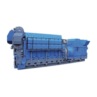
Figure 1: Function of expansion tank.
▪ Water connection in the top ensures easy and
simple installation and control under operation.
▪ Cooling water is absorbed in a rubber bag
which is hanging in the all-welded vessel.
▪ Corrosion of the all-welded vessel is excluded.
▪ The rubber bag is replaceable.
The expansion vessel should be connected to the
system at a point close to the cooling water inlet
connections (G1 / F1) in order to maintain positive
pressures throughout the system and allow expan-
sion of the water.
The safety valves are fitted on the manifold.
The pressure gauge is fitted on the manifold in such
a position that it can be easily read from the filling
point.
The filling point should be near the pressure expan-
sion vessel. Particularly the pressure gauge in such
a position that the pressure gauge can be easily
read from the filling point, when filling from the
mains water.
Automatic air venting valve should be fitted at the
highest point in the cooling water system.
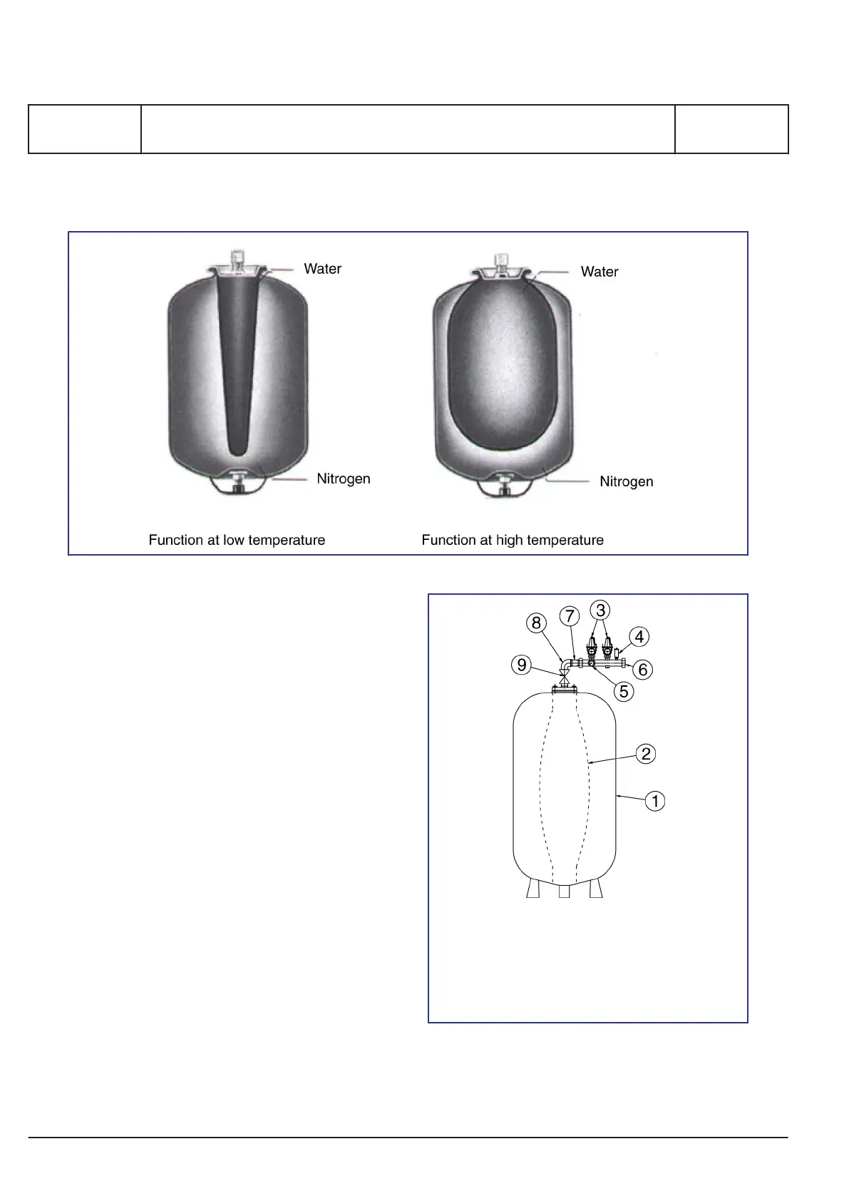
1 Pressure vessel 2 Exchangeable rubber bag
3 Safety valves 4 Automatic air venting valve
5 Pressure gauge 6 Manifold
7 Threaded pipe 8 Elbow
9 Shutt-off valve
Figure 2: Expansion tank
MAN Diesel & Turbo
T 13 01 1
Expansion tank pressurized
1671771-3.5
Page 2 (2)
L28/32S, L27/38S, L21/31S, L16/24S, L23/30DF, V28/32S-DF, V28/32H,
L28/32DF, V28/32S, L16/24, L21/31, L23/30H, L27/38, L28/32H
2016.02.24
 Loading...