Internal fuel oil system
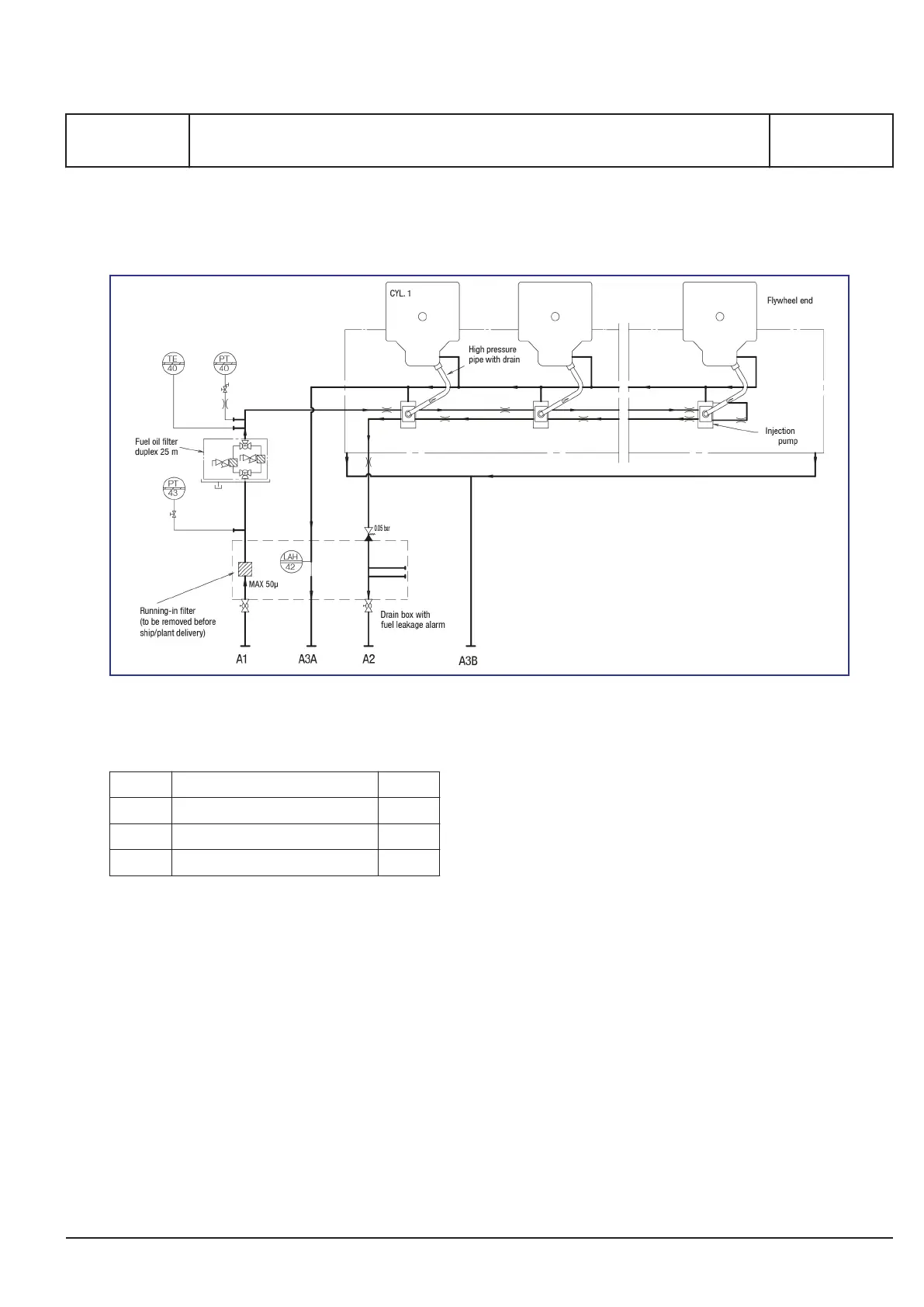
Figure 1: Diagram for fuel oil system (for guidance only, please see plant specific engine diagram)
Pipe description
A1 Fuel oil inlet DN 25
A2 Fuel oil outlet DN 25
A3A Clean leak oil to service tank DN 15
A3B Waste oil outlet to sludge tank DN 15
Table 1: Flange connections are standard according to DIN 2501
General
The internal built-on fuel oil system as shown in fig.
1 consists of the following parts:
▪ the running-in filter
▪ the high-pressure injection equipment
▪ the waste oil system
Running-in filter
The running-in filter has a fineness of 50 microns
(sphere passing mesh) and is placed in the fuel inlet
pipe. Its function is to remove impurities in the fuel
pipe between safety filter and the engine in the run-
ning-in period.
Note: The filter must be removed before ship deliv-
ery or before handling over to the customer.
It is adviced to install the filter every time the extern
fuel pipe system has been dismantled, but it is
important to remove the filter again when the extern
fuel oil system is considered to be clean for any
impurities.
Fuel oil filter duplex (Safety filter)
GenSets with conventional fuel injection system or
common rail fuel systems are equipped with a fuel
oil filter duplex, with a fineness of max. 25 microns
(sphere passing mesh) The fuel oil filter duplex is
with star-pleated filter elements and allows change-
over during operation without pressure-loss. The fil-
ter is compact and easy to maintain, requiring only
manual cleaning when maximum allowable pressure
drop is reached. When maximum pressure drop is
MAN Diesel & Turbo
3700163-4.1
Page 1 (2)
Internal fuel oil system
B 11 00 0
L27/38S, L27/38
2016.02.05 - Drain split
 Loading...