Crankcase ventilation
The crankcase ventilation is not to be directly con-
nected with any other piping system. It is preferable
that the crankcase ventilation pipe from each
engine is led independently to the open air. The out-
let is to be fitted with corrosion resistant flame
screen separately for each engine.
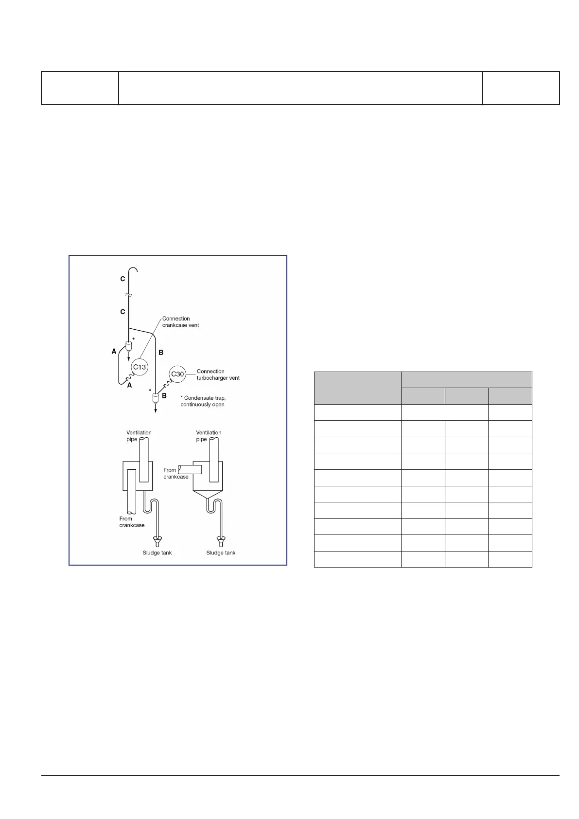
Figure 1: Crankcase ventilation
However, if a manifold arrangement is used, its
arrangements are to be as follows:
1) The vent pipe from each engine is to run inde-
pendently to the manifold and be fitted with
corrosion resistant flame screen within the
manifold.
2) The manifold is to be located as high as practi-
cable so as to allow a substantial length of pip-
ing, which separates the crankcase on the indi-
vidual engines.
3) The manifold is to be vented to the open air, so
that the vent outlet is fitted with corrosion
resistant flame screen, and the clear open area
of the vent outlet is not less than the aggregate
area of the individual crankcase vent pipes
entering the manifold.
4) The manifold is to be provided with drainage
arrangement.
The ventilation pipe must be designed to eliminate
the risk of water condensation in the pipe flowing
back into the engine and should end in the open air:
▪ The connection between engine (C13 / C30)
and the ventilation pipe must be flexible.
▪ The ventilation pipe must be made with continu-
ous upward slope of minimum 5°, even when
the ship heel or trim (static inclination).
▪ A continuous drain must be installed near the
engine. The drain must be led back to the
sludge tank.
Engine
Nominal diameter ND (mm)
A B C
L16/24, L16/24S 50 65
L21/31, L21/31S 65 40 80
L23/30H, L23/30S 50 - 65
L23/30DF, L23/30H* 50 25 65
L27/38, L27/38S 100 - 100
L28/32DF 50 40 65
L28/32H, L28/32S 50 - 65
V28/32H 100 - 125
V28/32DF 100 - 125
V28/32S 100 - 125
Table 1: Pipe diameters for crankcase ventilation
▪ Dimension of the flexible connection,
see pipe
diameters in table 1
.
▪ Dimension of the ventilation pipe after the flexi-
ble connection,
see pipe diameters in table 1
.
The crankcase ventilation flow rate varies over time,
from the engine is new/major overhauled, until it is
time to overhaul the engine again.
The crankcase ventilation flow rate is in the range of
3.5 – 5.0 ‰ of the combustion air flow rate [m³/h]
at 100 % engine load.
MAN Diesel & Turbo
1699270-8.7
Page 1 (2)
Crankcase ventilation
B 12 00 0
L28/32S, L27/38S, L23/30S, L21/31S, L16/24S, L23/30DF, V28/32S-DF, L28/32DF,
V28/32H, V28/32S, L16/24, L21/31, L23/30H, L27/38, L28/32H
2015.04.15 - (* Mk2)
 Loading...