EasyManua.ls Logo

Man L23/30DF User Manual

Man L23/30DF
392 pages
To Next Page IconTo Next Page
To Previous Page IconTo Previous Page
Page #320 background image
Adress Hex Bit Meas.
Point
Description Unit Origin Signal
range
MW 32
MW 33
MW 34
MW 35
MW 36
MW 37
MW 38
MW 39
MW 40
MW 41
MW 42
MW 43
20
21
22
23
24
25
26
27
28
29
2A
2B
TE12
TE01
TE21
TE40
TE31
TE98-1
TE98-2
TE98-3
TE38
TE10
TE27-1
TE27-2
HT cooling water temperature engine outlet
LT cooling water temperature air cooler inlet
Lube oil temperature filter inlet
Fuel oil temperature engine inlet
Charge air temperature cooler outlet
Alternator windwing temperature L1
Alternator windwing temperature L2
Alternator windwing temperature L3
Ambient air temperature
HT cooling water temperature engine inlet
Alternator front bearing temperature
Alternator rear bearing temperature
CMS
CMS
CMS
CMS
CMS
CMS
CMS
CMS
CMS
CMS
CMS
CMS
0 - 200
0 - 200
0 - 200
0 - 200
0 - 200
0 - 200
0 - 200
0 - 200
0 - 200
0 - 200
0 - 200
0 - 200
MW 48 30 0
1
2
3
4
5
6
7
8
9
10
11
Sensor fault TE12 :
HT cool water temp. engine outlet
Sensor fault TE01 :
LT cool water temp. air cooler inlet
Sensor fault TE21 : Lube oil temperature filter inlet
Sensor fault TE40 : Fuel oil temperature engine inlet
Sensor fault TE31 : Charge air temp. cooler outlet
Sensor fault TE98-1 : Alternator windwing temp. L1
Sensor fault TE98-2 : Alternator windwing temp. L2
Sensor fault TE98-3 : Alternator windwing temp. L3
Sensor fault TE38 : Ambient air temperature
Sensor fault TE10 :
HT cool. water temp. engine inlet
Sensor fault TE27-1 : Alternator front bearing temp.
Sensor fault TE27-2 : Alternator rear bearing temp.
CMS
CMS
CMS
CMS
CMS
CMS
CMS
CMS
CMS
CMS
CMS
CMS
binary
binary
binary
binary
binary
binary
binary
binary
binary
binary
binary
binary
MW 64
MW 65
MW 66
MW 67
MW 68
MW 69
MW 70
MW 71
MW 72
MW 73
MW 74
MW 75
MW 76
40
41
42
43
44
45
46
47
48
49
4A
4B
4C
PT10
PT01
PT21
PT22
PT23
PT40
PT31
PT70
PT43
ZT59
ZT45
PT38
HT cooling water pressure
LT cooling water pressure
Lube oil pressure filter inlet
Lube oil pressure filter outlet
Lube oil pressure TC
Fuel oil pressure engine inlet
Charge air pressure cooler outlet
Start air pressure
Fuel oil pressure filter inlet
Alternator load
Fuel rack position
Ambient air pressure
Analog speed setpoint
CMS
CMS
CMS
CMS
CMS
CMS
CMS
CMS
CMS
CMS
CMS
CMS
CMS
MW 80 50 0
1
2
3
4
5
6
7
8
9
10
11
12
Sensor fault PT10 : HT cooling water pressure
Sensor fault PT01 : LT cooling water pressure
Sensor fault PT21 : Lube oil pressure filter inlet
Sensor fault PT22 : Lube oil pressure filter outlet
Sensor fault PT23 : Lube oil pressure TC
Sensor fault PT40 : Fuel oil pressure engine inlet
Sensor fault PT31 : Charge air press. cooler outlet
Sensor fault PT70 : Start air pressure
Sensor fault PT43 : Fuel oil pressure filter inlet
Sensor fault ZT59 : Alternator load
Sensor fault ZT45 : Fuel rack position
Sensor fault PT38 : Ambient air pressure
Sensor fault : Analog speed setpoint
CMS
CMS
CMS
CMS
CMS
CMS
CMS
CMS
CMS
CMS
CMS
CMS
CMS
binary
binary
binary
binary
binary
binary
binary
binary
binary
binary
binary
binary
binary
MAN Diesel & Turbo
B 19 00 0
Modbus list
3700054-4.0
Page 2 (5)
L27/38S, L16/24S, L21/31S, L16/24, L21/31, L27/38
2015.11.27

Table of Contents

Question and Answer IconNeed help?

Do you have a question about the Man L23/30DF and is the answer not in the manual?

Man L23/30DF Specifications

General IconGeneral
BrandMan
ModelL23/30DF
CategoryPortable Generator
LanguageEnglish

Summary

I 00 Introduction

Introduction to project guide

Provides information and data for planning new plants with MAN Diesel & Turbo engines.

Key for engine designation

Explains the coding system for identifying MAN Diesel & Turbo engines.

Code identification for instruments

Details the coding system for measuring devices and instruments.

Symbols for piping

Lists and explains common symbols used in piping diagrams.

D 10 General information

List of capacities

Provides technical data and specifications for various engine components and systems.

Vibration limits and measurements

Specifies acceptable vibration limits and measurement points for the GenSet.

Description of sound measurements

Details the methodology and standards for measuring sound power levels.

Emission limits Worldbank II

Outlines emission limits according to Worldbank II for plants up to 300 MWth.

Overhaul recommendation, Maintenance and Expected life time

Details recommended overhaul intervals, maintenance, and component life times.

B 10 Basic diesel engine

General description

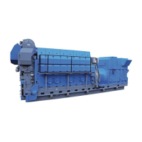
Provides a general overview of the engine's construction and features.

Main particulars

Lists the key technical specifications and performance data of the engine.

Dimensions and weights

Presents the physical dimensions and weights of the GenSet for different cylinder configurations.

B 11 Fuel oil system

Internal fuel oil system

Describes the components and functions of the engine's internal fuel oil system.

Specification of heavy fuel oil (HFO)

Details the requirements and properties for heavy fuel oil (HFO) used in MAN engines.

Specification of diesel oil (MDO)

Outlines the properties and specifications for Maritime Diesel Oil (MDO).

Specification of gas oil/diesel oil (MGO)

Lists the properties and specifications for gas oil/diesel oil (MGO).

Crude oil specification

Details the specifications for using crude oil directly from oil wells with MAN engines.

Viscosity-temperature diagram (VT diagram)

Explains how to use the VT diagram to determine fuel temperature and viscosity.

Calculation of specific fuel oil consumption (SFOC)

Explains the standardized calculation method for SFOC conversion between conditions.

Fuel oil consumption for emissions standard

Presents fuel consumption data for emissions standards at various load conditions.

Fuel injection valve

Describes the design and function of the fuel injection valve.

Fuel oil filter duplex

Explains the function and installation of the fuel oil filter duplex.

B 12 Lubricating oil system

Internal lubricating oil system

Details the components and flow of the internal lubricating oil system.

Quality of oil

Specifies the required quality and type of lubricating oil for MAN engines.

Lubricating oil consumption

Provides information on calculating and monitoring specific lubricating oil consumption (SLOC).

Treatment and maintenance of lubricating oil

Covers methods for treating and maintaining lubricating oil for optimal performance.

Criteria for cleaning/exchange of lubricating oil

Provides criteria for evaluating lubricating oil condition and determining replacement needs.

B 13 Cooling water system

Specification of engine coolant

Details the composition and required quality specifications for engine coolant.

Quality of raw-water in cooling tower operation (additive and circulating water)

Specifies the basic demands made on cooling water quality for cooling tower operation.

Quality of water used in exhaust gas boiler plants

Lists quality requirements for water used in exhaust gas boiler plants.

Internal cooling water system

Describes the engine's internal cooling water system, including circuits and components.

Design data for the external cooling water system

Provides data for dimensioning auxiliary machinery in the external cooling water system.

Expansion tank pressurized

Details expansion tank volume requirements and installation for cooling water systems.

B 14 Compressed air system

Specification of compressed air

Outlines quality requirements for compressed air for various engine systems.

Compressed air system

Details the components of the engine's compressed air system, including starting and control.

B 15 Combustion air system

Combustion air system

Explains the combustion air requirements, including intake, turbocharger, and coolers.

Specifications of intake air (combustion air)

Lists quality requirements and limit values for intake air (combustion air).

Water washing of turbocharger - compressor

Describes the procedure for water washing the turbocharger compressor.

B 16 Exhaust gas system

Internal exhaust gas system

Describes the flow of exhaust gas from valves to the turbocharger and exhaust pipe system.

External exhaust gas system

Covers requirements for exhaust piping, back-pressure, and mounting.

Pressure droop in exhaust gas system

Provides a nomogram and calculation method for pressure drop in exhaust gas piping.

SCR (Selective Catalytic Reduction)

Introduces MAN's SCR technology for optimizing emissions and engine performance.

B 17 Speed control system

Starting of engine

Outlines procedures for starting the engine on HFO and MDO, including preheating and prelubrication.

Power Management - Alternator protection

Provides guidelines and recommendations for power management and alternator protection systems.

Actuators

Describes the electro-hydraulic actuators used for speed control in the engines.

B 19 Safety and control system

Operation data and set points

Lists normal values, alarm set points, and auto-stop parameters for engine operation.

Modbus ASCII protocol

Explains the Modbus ASCII protocol used for communication with SaCoSone GENSET.

Modbus list

Provides a list of Modbus registers for accessing engine data and alarms.

Oil mist detector

Details the oil mist detector, its function, and technical specifications.

B 20 Foundation

Resilient mounting system for landbased generating sets

Covers mounting of base plates on concrete foundations and resilient mounting systems.

B 21 Test running

Shop test programme for power plants

Outlines the shop test program for power plants, including operating points and load application.

E 23 Spare parts

Weight and dimensions of principal parts

Shows weights and dimensions of major engine components like cylinder head, piston, and liners.

Spare parts for unrestricted service

Lists standard spare parts for unrestricted service, categorized by engine component.

P 24 Tools

Introduction to spare part plates for tools

Introduces three tool packages: standard, additional, and hand tools.

Standard tools for normal maintenance

Lists standard tools for normal maintenance, including cylinder head tools.

Additional tools

Lists additional tools, including grinding machines for valves and seats.

Hand tools

Lists hand tools for normal maintenance, including socket sets and spanners.

B 50 Alternator

Alternators for GenSets

Describes the design, types, and specifications of alternators used for GenSets.

Alternator cable installation

Provides guidelines for installing alternator cables, including routing and earth connection.

B 98 Preservation and packing

Lifting instruction

Details the safe lifting procedure for complete generating sets using specified tools and straps.

Related product manuals