GROVE Published 10-21-2010, Control# 198-04 6-11
5540F/YB5515 SERVICE MANUAL ENGINE AND ENGINE SYSTEMS
ENGINE FUEL SYSTEMS
Fuel Injected Dual Fuel System
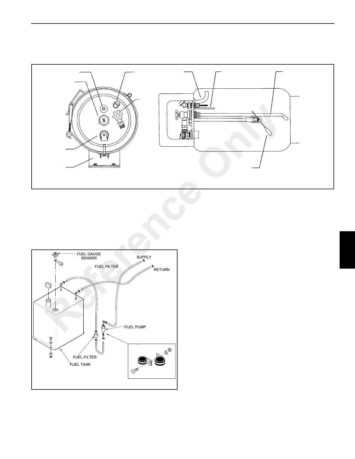
Gasoline Portion
The gasoline fuel portion of this dual fuel system Figure 6-7
is a closed-loop system which includes a fuel tank, an in-line
fuel pump, a filter installed between the fuel pump and the
engine. A relay switches between Liquid Propane Gas (LPG)
and Gasoline when the dual fuel switch is actuated in the
operator’s cab.
Liquid Propane Gas (LPG) Portion
The LPG portion of the dual fuel system includes an LPG
tank, a bulkhead connection, a hydrostatic relief valve, an in-
line filter, a primary vaporizer unit, a secondary vaporizer unit
and a throttle body. A relay switches between Liquid Propane
Gas (LPG) and Gasoline when the dual fuel switch is
actuated in the operator’s cab.
LPG Tank
See Figure 6-6 for description of LPG tank.
In-line Filter
A 20 micron filter Figure 6-8 is installed in the LPG line to the
engine. This filter must be replaced yearly.
Hydrostatic Relief Valve
The hydrostatic relief valve Figure 6-8 protects the LPG fuel
system from a pressure buildup above 375 psi (2585 kPa). If
the pressure in the system becomes greater than the setting
of the relief valve, the relief valve opens and releases gas to
the atmosphere until the pressure drops below the relief
valve setting, at which time the relief valve closes.
FIGURE 6-6
a0959
LPG Tank
1
2
3
4
5
6
7
8
9
10
FIGURE 6-7
a2184
Dual Fuel Gasoline System
Reference Only

 Loading...


