HYDRAULIC SYSTEM 5540F/YB5515 SERVICE MANUAL
4-12 Published 10-21-2010, Control# 198-04
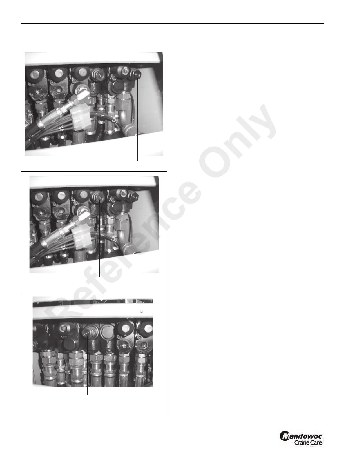
Main Relief Valves
Each pump section has a main relief valve to protect the
hydraulic circuits fed by the section. Pump sections 1, 2 and
3 are in the inlet and mid-inlet sections of the main control
valve. See Figure 4-6, Figure 4-7 and Figure 4-8.
The relief valve for the fourth section is located in the priority
flow control valve.
The purpose of the main relief valve is to control maximum
pressure in the hydraulic pump circuit. Pressure in the
system increases as resistance to the flow of hydraulic oil
increases. The hydraulic pump operates constantly and will
continue to push more hydraulic oil into the system. When
the flow of the hydraulic oil is stopped at any point in the
system, pressure increases very rapidly. The relief valve
opens and lets the hydraulic oil from the hydraulic pump
return to the hydraulic tank when the pressure reaches the
maximum set limit of the relief valve.
Remember, pressure in a hydraulic system is applied to
every component in contact with the hydraulic oil. For
example, pressure will increase when a cylinder rod reaches
the end of its stroke. This pressure will have an affect on
every component between the cylinder and the hydraulic
pump. Without a relief valve in the circuit, the high pressure
can easily break the hydraulic pump, a hydraulic line or other
component in that circuit.
FIGURE 4- 6
p0709
Swing Main Relief Valve Location
FIGURE 4-7
p0710
Telescope/Outrigger Main relief Valve Location
FIGURE 4-8
p0706
Winch Hoist/Boom Lift Main Relief Valve
Location
Reference Only

 Loading...


