STRUCTURALS 5540F/YB5515 SERVICE MANUAL
11-16
MAIN WINCH (TULSA MODEL)
Theory Of Operation
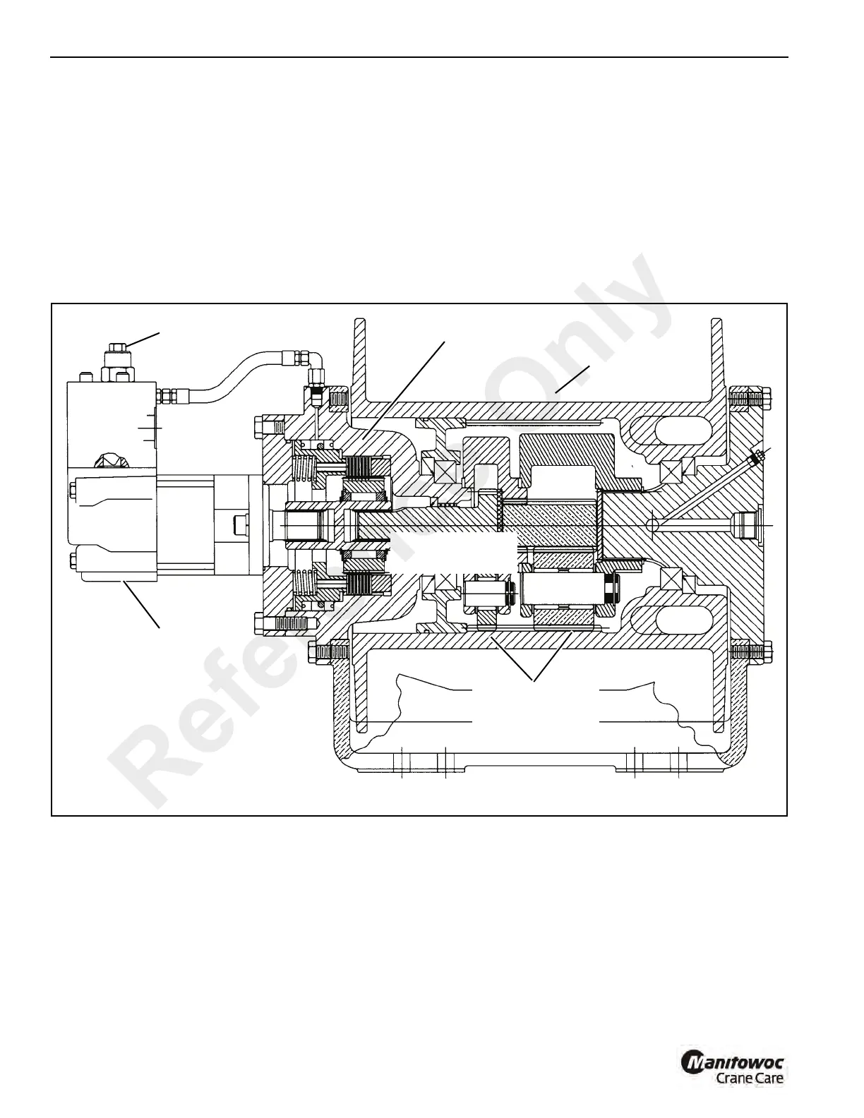
The main winch design (Figure 11-17) is composed of a high
speed, low torque gerotor motor, driving through a multiple
disc brake, through a pair of planet gear sets to the cable
drum.
The multiple disc brake is spring applied and hydraulically
released through a port in the brake housing. During in-haul
(Figure 11-18) the brake is not released, since the load is
driven through a one-way cam clutch, bypassing the brake.
When the load comes to a stop, the cam clutch locks up and
the load is inhibited from moving by the brake. During payout
(Figure 11-19), a counterbalance valve is used to inhibit the
load from moving faster than desired. The counterbalance
valve partially blocks the main line from the motor back to the
control valve, allowing only a limited amount of oil through
the motor. The counterbalance valve modulates by sensing
pressure on the other mainline, the line from the main control
valve to the motor. Also, anytime there is sufficient pressure
to modulate the counterbalance valve, this same pressure
releases the multiple disc brake.
FIGURE 11-17
Typical Main Winch Assembly - Cut-Away View
a0472
Counterbalance
Valve
Planet Gear
Assembly
Counterbalance
Valve
Winch Motor
Winch Drum
Winch Brake
Reference Only

 Loading...


