GROVE Published 10-21-2010, Control# 198-04 7-9
5540F/YB5515 SERVICE MANUAL TRANSMISSION AND TORQUE CONVERTER
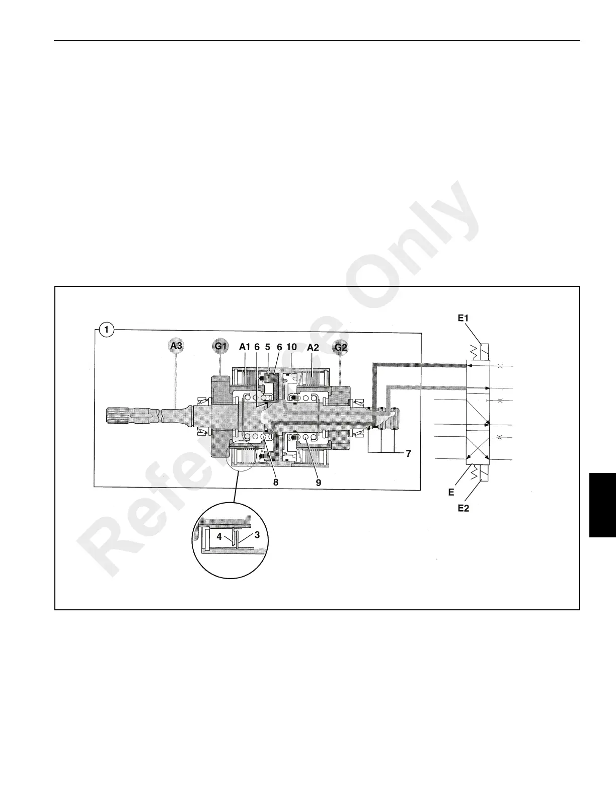
Reverser Clutch
The reverser clutch unit 1(See Figure 7-9) transfers drive
from the input shaft A3 to either gear G1 or gear G2
depending on which of the two clutches (A1 or A2) is
engaged, giving forward or reverse drive. When neither
clutch is engaged, neutral is selected.
The clutches are of the wet, multi-plate type.
The clutch housings and input shaft are a one piece
assembly A3. The assembly is permanently driven by the
engine via the torque converter. Clutch counter plates 3 are
also permanently driven via meshing teeth inside the clutch
housings. Clutch friction plates 4 are meshed with the gear/
plate carriers, (G1 and G2).
In the diagram, clutch A1 is engaged. The counter plates 3
and friction plates 4 are pressed together by hydraulically
actuated piston 5. Drive is then transmitted from the input
shaft to the gear G1. Clutch A2 is disengaged and no drive is
transmitted to gear/plate carrier G2. The gear is also free to
rotate on the input shaft assembly.
Actuation of the hydraulic pistons 10 and 5 is controlled via
three position solenoid valve E. When neutral is selected,
solenoids E1 and E2 are deactivated and the flow of
pressurised oil to the clutches is blocked. Springs 8 and 9
move the pistons away from the clutch plates and oil from
both pistons is vented to the sump. When either forward or
reverse is selected, the solenoid valve E diverts pressurised
oil via cross drillings inside the input shaft A3 to the
appropriate clutch (piston 10 or 5) in the unit. Pressure from
the other clutch is vented to the sump via the solenoid valve
spool. Oil is prevented from leaking by seals 6 on the pistons
and ring seals 7 on the input shaft A3.
The valve E is shown using symbols.
Reference Only

 Loading...


