GROVE Published 10-21-2010, Control# 198-04 4-7
5540F/YB5515 SERVICE MANUAL HYDRAULIC SYSTEM
Table 4-6
Swing Circuit Troubleshooting
SUCTION, PRESSURE AND RETURN
CIRCUITS
General
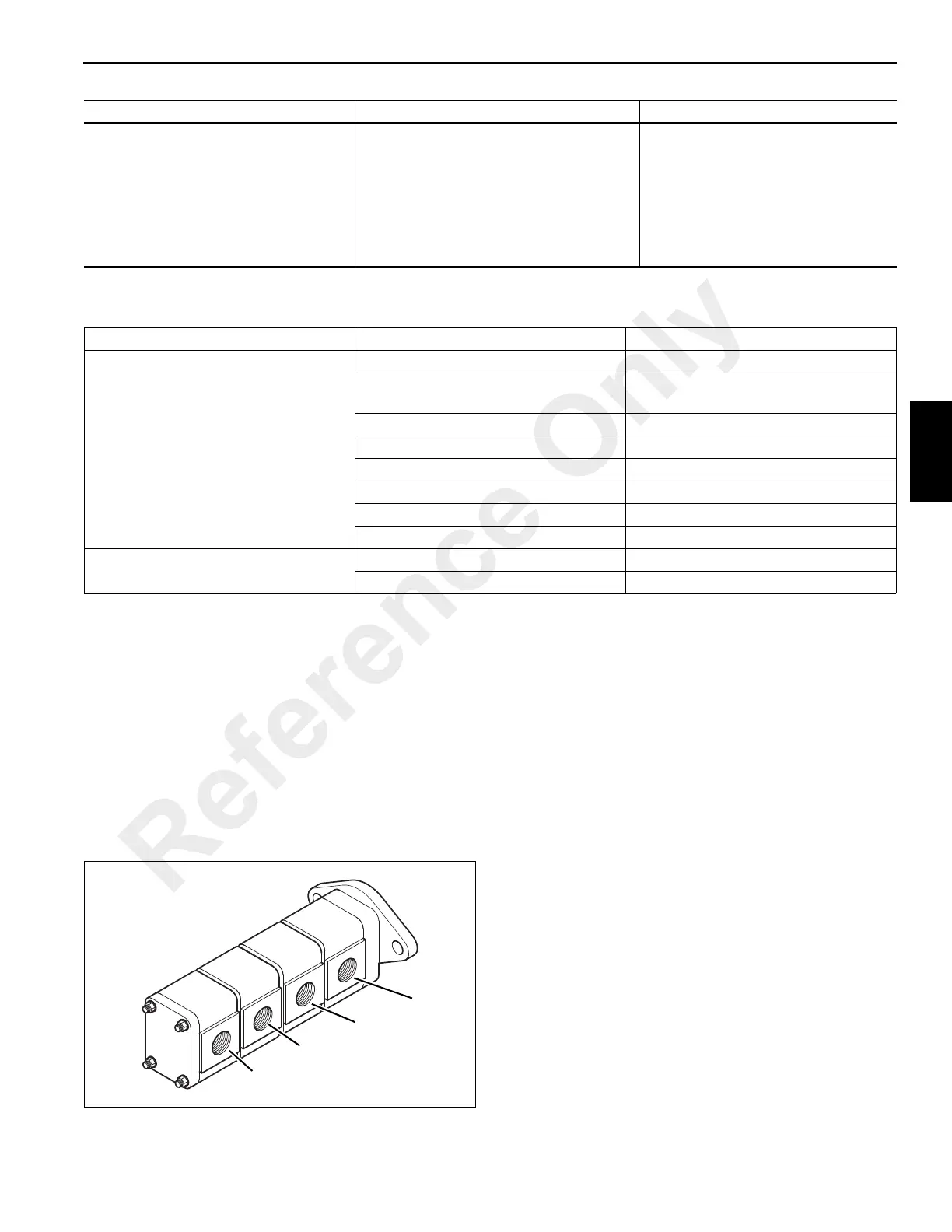
The main hydraulic pump is a gear pump with four sections
Figure 4-1. Oil is available to the inlet of the pump from the
hydraulic tank. The first pump section (nearest to the
transmission) moves the hydraulic oil to the P3 port of the
main control valve. Here the oil is available to operate the
main winch. Hydraulic oil returning from the winch motor
passes through the control valve, the return filter and then
into the hydraulic oil tank.
The second pump section moves hydraulic oil to the P2 port
of the main control valve. At this valve, the oil is available to
operate the lift and crowd and outrigger cylinder functions.
Hydraulic oil which returns from these functions is sent
through the return filter, then back to tank.
The third pump section moves hydraulic oil to the P1 port of
the control valve. Oil is available to operate the swing
function. Hydraulic oil which returns from this functions is
sent through the return filter, then back to tank.
The fourth pump section moves hydraulic through to the
steering orbitrol and the accumulator charging valve, through
a priority flow control valve. Return oil from the steering
orbitrol returns to tank through the return filter.
Hydraulic Pump
The drive gears of the four gear sets are turned by the drive
shaft connected to the transmission. When the gears turn, oil
from the inlet side of the hydraulic pump is moved around the
outside of the gears to the outlet side of the pump.
The inlet side of the hydraulic pump is under low pressure
Figure 4-2. The outlet side is normally under high pressure.
Pressure from the outlet side of the pump pushes the
pressure plates against the gears to inhibit leakage or
bypass in the hydraulic pump.
Hook block lowers, but will not raise. Malfunction in anti-double blocking
electrical system.
See Electric System, Chapter 3.
Bad cartridge in anti-double blocking
solenoid valve.
Faulty controller.
Faulty controller. Repair or replace.
Restriction in pilot control line to control
valve.
Locate and correct.
Problem Possible Cause Remedy
Problem Possible Cause Remedy
Mast will not rotate when the swing
control is actuated.
Damaged or broken motor shaft. Repair or replace the swing motor.
Damaged or broken gearbox shaft or
gear.
Overhaul or replace the gearbox. See
Structurals, Chapter 11.
Faulty pump. Overhaul or replace the pump.
Leakage in hydraulic swivel. Replace seals in the swivel.
Main relief valve malfunction. Check main relief pressure.
Dirt or restriction in swing relief. Clean the relief valve.
Low pilot pressure. Check and adjust.
Faulty controller. Repair or replace.
Difficult or slow swing. Friction or restriction in mast bearing. See Structurals, Chapter 11.
Faulty swing motor or gearbox. Repair or replace.
FIGURE 4-1
a1619
Pump
Section 4
Pump
Section 3
Pump
Section 2
Pump
Section 1
Reference Only

 Loading...


