Section 2 Installation Instructions
Part Number 000007345 2/14 21
NON-MANITOWOC MULTI-CIRCUIT CONDENSER SIZING CHART
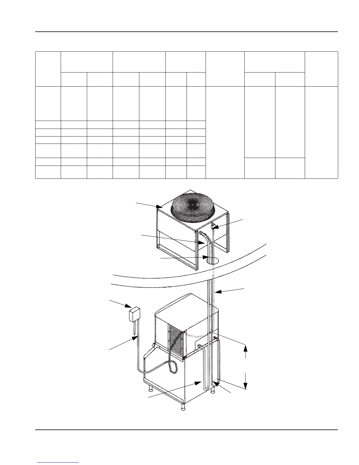
Typical Single Circuit Remote Condenser Installation
Ice
Machine
Model
Refrigerant Heat of Rejection
Internal
Condenser
Volume (cu ft)
Design
Pressure
Quick Connect Stubs-
Male Ends
Head
Pressure
Control
Valve
Type Charge
Average
Btu/hr
Peak
Btu/hr
Min Max Discharge Liquid
I0590 R-404A
6 lbs. 6,100 6,900 0.020 0.035
500 psig
(3447 kpa)
(34.47 bar)
safe working
pressure
coupling
P/N
83-6035-3
coupling
P/N
83-6034-3
Manitowoc
P/N
83-6809-3
I0690 R404A 6.5 lbs. 9,000 13,900 0.045 0.060
I0890 R-404A 8.5 lbs. 13,000 16,000 0.045 0.060 2,500 psig
(17237 kpa)
(172.37 bar)
burst
pressure
I0990 R-404A 7 lbs. 13,000 16,000 0.045 0.060
I1090
I1190
R-404A
8.5 lbs. 16,250 18,600 0.045 0.060
no
substitutes
I1490 R-404A 11 lbs. 23,500 27,000 0.085 0.105 mounting
flange P/N
83-6006-3
mounting
flange P/N
83-6005-3
I1890 R-404A 12.5 lbs. 30,000 35,000
0.085 0.105
SINGLE CIRCUIT
REMOTE CONDENSER
ELECTRICAL
DISCONNECT
DISCHARGE
LINE
LIQUID LINE
ELECTRICAL
DISCONNECT
ELECTRICAL
SUPPLY
ICE MACHINE
BIN
DISCHARGE
REFRIGERANT
LINE
LIQUID
REFRIGERANT
LINE
36.00"
(91.44 cm)
DROP
TO ICE MACHINE
F1 & F2
 Loading...