Manitowoc Published 11-22-17, Control # 257-02 4-1
MLC300 SERVICE/MAINTENANCE MANUAL BOOM
SECTION 4
BOOM
GENERAL MAINTENANCE
This section contains maintenance and adjustment
instructions for the limit devices used with the boom and the
luffing jib attachment.
For maintenance and inspection of the following
components, see the Service/Maintenance Manual supplied
with your crane:
• Straps
• Wire rope
• Load block and weight ball
• Boom and jib
BOOM AND LUFFING JIB ANGLE
INDICATOR CALIBRATION
An angle sensor (see Figure 4-1) is located inside the boom
and luffing jib tops. The sensors are calibrated on the rated
capacity limiter/rated capacity indicator (RCL/RCI) display
and do not require adjustment.
BOOM STOP LIMIT SWITCH
When the boom is at a position other than the maximum
allowable angle, the limit switch in the boom stop switch unit
(1, Figure 4-2
) is closed, providing a continuous 24 V
DC
signal to the ID01 input on the IOLC30 control module.
If the boom reaches the maximum allowable angle for your
boom/jib configuration, the limit switch will open (voltage at
the ID01 input drops to 0 V
DC
), signaling the control system
to stop the boom hoist and apply the hoist brake.
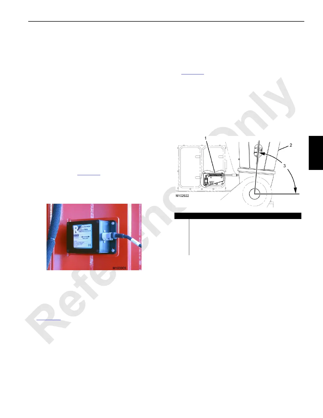
Automatic Boom Stop Overview
See Figure 4-2 for the following.
The boom stop switch unit (1) automatically stops the boom
and applies the boom hoist brake if the boom is raised to the
maximum switch boom angle (3).
NOTE: The maximum switch boom angle is greater than
the maximum boom angle to allow the operator to
boom up past the maximum capacity chart angle to
get to the minimum chart radius with a load on the
hook and the boom deflected.
Item Description
1 Boom Stop Switch Unit
2 Boom Butt
3 Maximum Switch Boom Angle:
84.5°—Boom with EUBP
86.5°—Boom Only
87.5°—Boom with Luffing Jib
FIGURE 4-2

 Loading...


