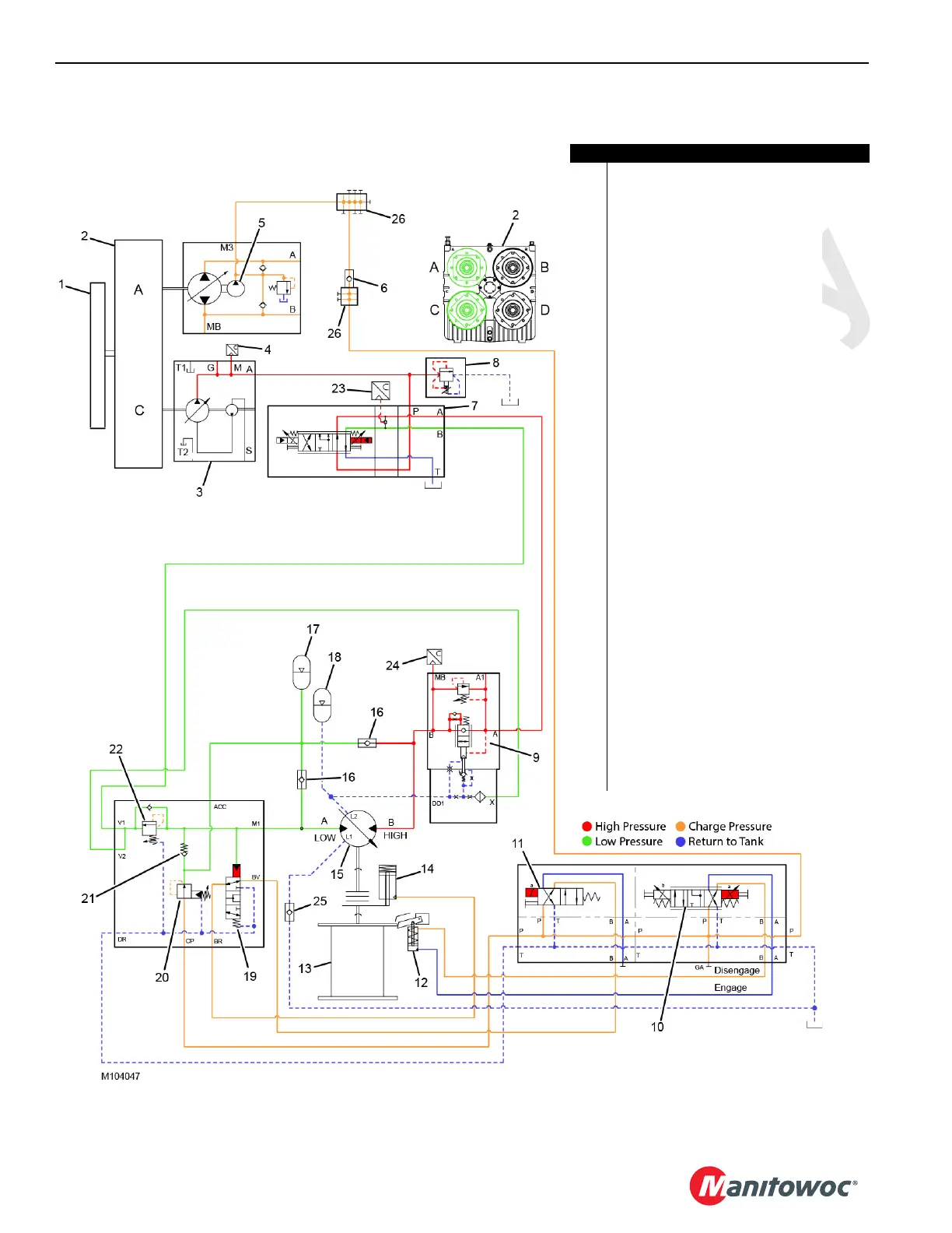
FIGURE 5-11
Item Description
1 Engine
2 Pump Drive
3 Pump 3 (inboard C) (right/system B)
4 Pump 3 Pressure Transducer
5 Pump 1 Charge Pump (inboard A)
6 Check Valve
(cracking pressure = 0,34 bar [5 psi])
7 Drum 6 System B Control Valve
8 Relief Valve
(370—375 bar [5,366—5,439 psi])
9 Load-Holding Valve
(shifting pressure= 12 bar [174 psi])
10 Pawl Valve
11 Drum 6 Brake Release Solenoid Valve
12 Drum 6 Pawl Cylinder
13 Drum 6
14 Drum Brake (spring applied)
15 Hydraulic Motor (variable 160/82 cc/rev)
16 Makeup Check Valve (qty 2)
(cracking pressure = 0,34 bar [5 psi])
17 Makeup Accumulator
(precharge = 8,3 bar [120 psi])
18 Thermal Expansion Accumulator
(precharge = 1,4 bar [20 psi])
19 Brake Defeat Valve
20 Pressure-Reducing Valve
(16,5 bar [240 psi])
21 Check Valve
(cracking pressure = 0,2 bar [3 psi])
22 Sequence Valve (21,4 bar [310 psi])
23 Drum 6 System B Pressure
Transducer (ports A/B)
24 Drum 6 Motor Pressure Transducer
25 Check Valve
(cracking pressure = 0,34 bar [5 psi])
26 Distribution Manifold (qty 2)

 Loading...


