POWER TRAIN MLC300 SERVICE/MAINTENANCE MANUAL
7-4
Published 11-22-17, Control # 257-02
NOTE: Overcharging shortens a battery’s life.
If the battery becomes hot to the touch or if it
gasses violently, temporarily halt charging or
reduce the charging current.
Storage
When the crane is left idle for prolonged periods, the
batteries should be periodically charged.
When storing batteries, make sure they are fully charged to
prevent sulfation and the possibility of freezing.
Follow your battery dealer’s recommendations.
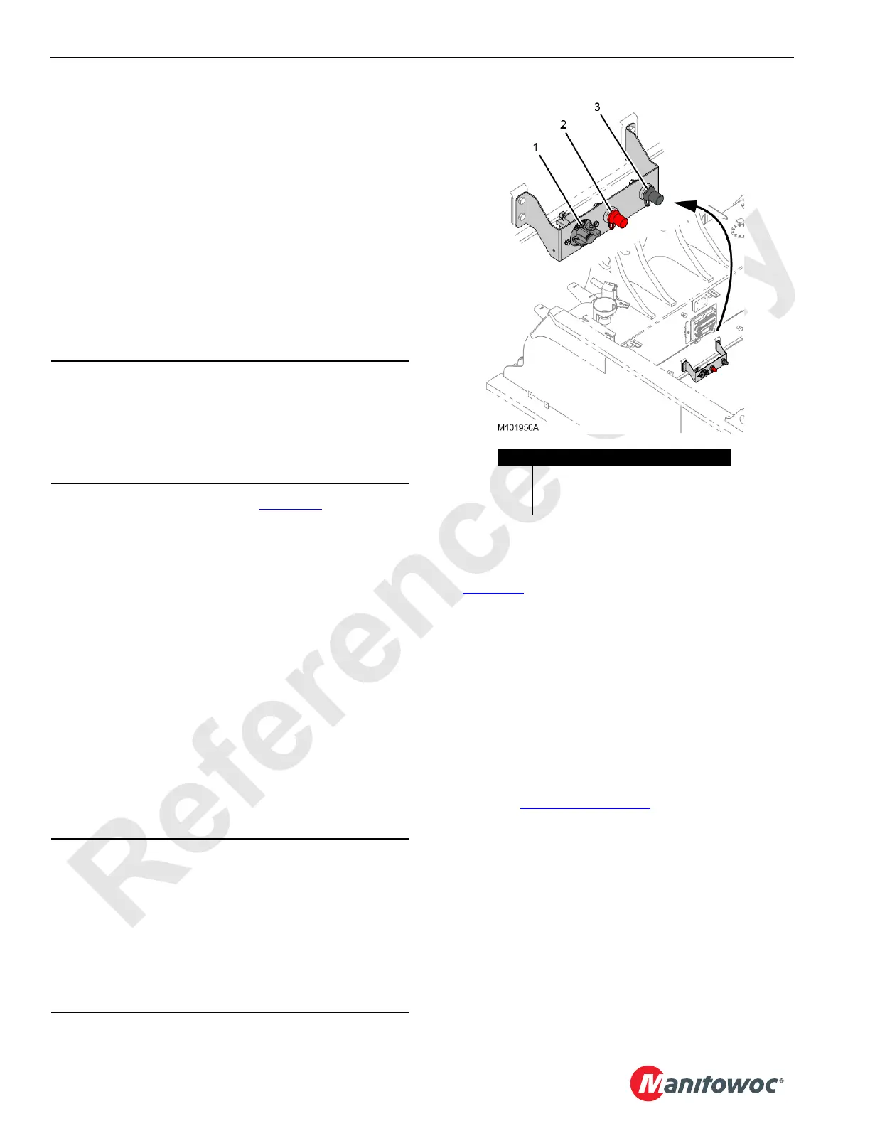
BATTERY DISCONNECT SWITCH
The battery disconnect switch (1, Figure 7-3) is located on
the rear of the rotating bed. It can be locked with a padlock in
either position, ON or OFF.
The switch disconnects the positive side of the batteries from
the crane’s electrical control system.
Turn the switch handle counterclockwise to turn off
(disconnect) the batteries from the electrical control system.
Turn the switch handle clockwise to turn on (connect) the
batteries to the electrical control system.
Use the disconnect switch under the following
circumstances:
• When servicing the crane’s electrical control system
• To help prevent the batteries from discharging when the
crane is stored for extended periods of time
• To prevent the crane from being started by unauthorized
personnel
BATTERY CHARGER (OPTIONAL)
See Figure 7-4 for the following procedure.
An optional auxiliary power unit (APU) equipped with a
10 KW, continuous duty, 60 HZ AC generator and a DC
charging system is available from Manitowoc Cranes for the
following operations when the crane engine is off:
• To power the cab heater and air conditioner
• To charge the crane batteries
• To power the cold weather heaters
• To power any AC lighting the crane is equipped with
If an alternative method of charging is desired, follow the
instructions in Charging on page 7-3
.
The APU can be started with the switch in the operator cab.
If the crane is not to be used for more than a few days, the
charger should be plugged into a 240 V
AC
source.
There is a 10 A fuse on the DC output. For charger
troubleshooting and maintenance information, refer to the
manufacturer’s service manual.
CAUTION
Avoid Electronic Control Module Malfunction!
Before disconnecting the battery disconnect, make sure
the engine ignition switch has been off for five minutes.
This will avoid engine fault codes and undesirable
operation.
CAUTION
Avoid Control System Damage!
Before welding:
• Disconnect the battery cables at the batteries.
• Disconnect the cabling from any control modules that
are in the vicinity of the welding.
Do not rely on the battery disconnect switch to protect the
crane’s electronic control systems when welding.
FIGURE 7-3
Item Description
1 Battery Disconnect Switch
2 Remote Positive Battery Terminal
3 Remote Negative Battery Terminal

 Loading...


