HOISTS MLC300 SERVICE/MAINTENANCE MANUAL
5-36
Published 11-22-17, Control # 257-02
DRUM 2/3 MINIMUM BAIL LIMIT (NON-FREE
FALL DRUM)
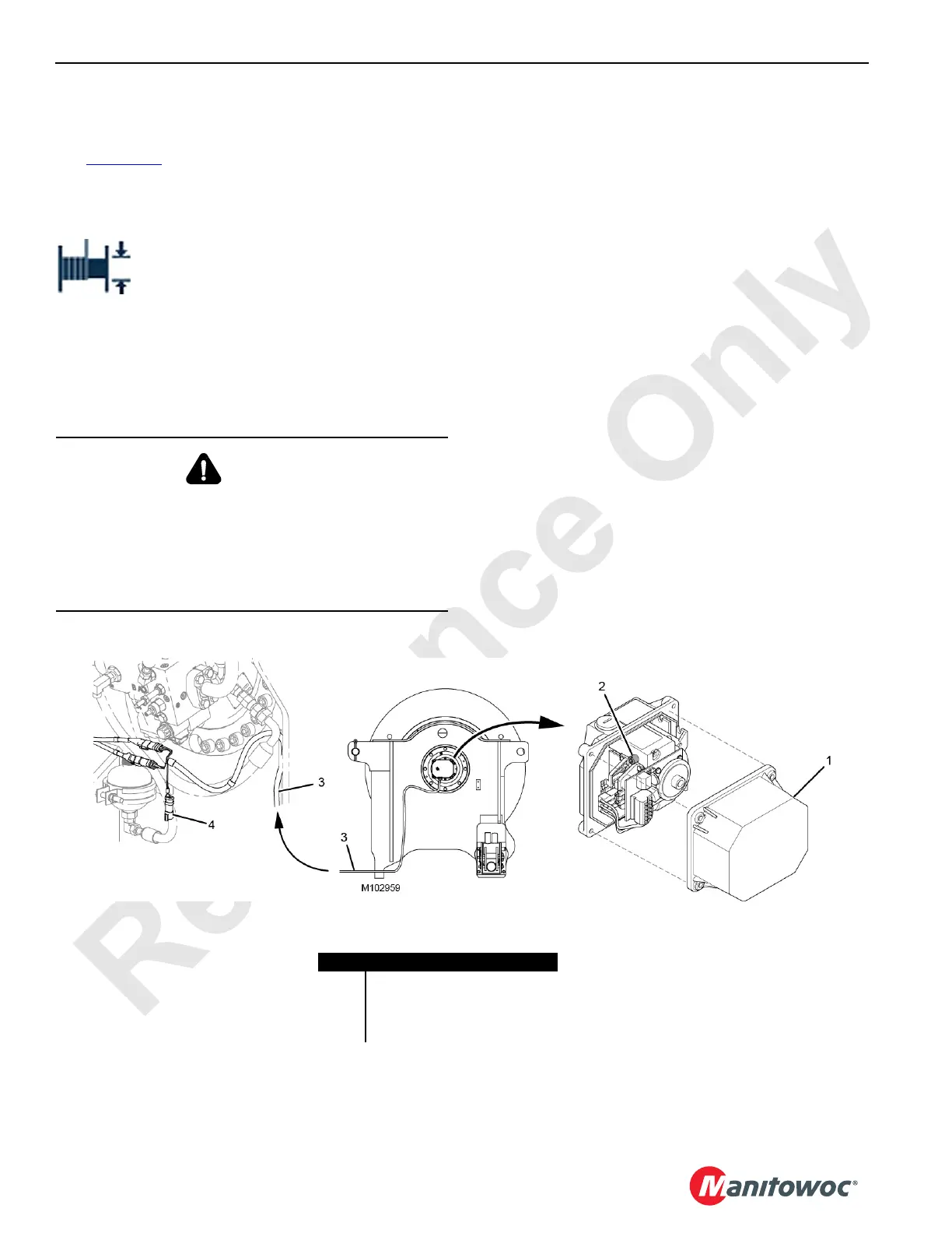
See Figure 5-19 for the following procedures.
The minimum bail limit stops drum 2 or drum 3 from lowering
when there are three to four wraps of wire rope remaining on
the drum.
When the limit is reached, the operating limit
fault is activated and the fault icon appears in
the fault bar of the Main Display Working
Screen.
• The drum can be operated in the hoist direction after the
limit is contacted.
• The limit can only be bypassed by disconnecting the
electric cable from the limit switch and connecting the
supplied shorting plug (4).
Pre-Adjustment
1. Pay out the wire rope from the desired drum 2 or drum 3
until there are three to four wraps of rope on the first
layer of the drum.
2. Lockout-tagout the crane.
Limit Switch Adjustment
1. Remove the cover with gasket (1).
2. Turn the limit switch screw (2) until you hear the switch
activate (click). Also, you can verify the state of the limit
switch in the digital input screen of the main display.
3. Start the engine and check for proper operation, as
follows:
a. Haul in wire rope on the drum until there are 6-7
wraps on the first layer of the drum.
b. Pay out wire rope from the drum. The drum must
stop and the operating limit alert must come on
when there are 3-4 wraps on the first layer of the
drum.
c. Readjust the limit switch as needed.
4. Install the cover with a new gasket (if required).
WARNING
Falling Load Hazard!
When lowering a load below the minimum bail limit, do so
slowly with extreme caution. Do not lower the load to the
point where less than three full wraps of wire rope are on
the drum. The wire rope could be pulled out of the drum,
allowing the load to fall.
Item Description
1 Cover with Gasket
2 Limit Switch Screw
3 Electric Cable
4 Shorting Plug
Left Side of Drum 2/3
Right Side of Drum 2/3
FIGURE 5-19

 Loading...


