Manitowoc Published 11-22-17, Control # 257-02 2-15
MLC300 SERVICE/MAINTENANCE MANUAL HYDRAULIC SYSTEM
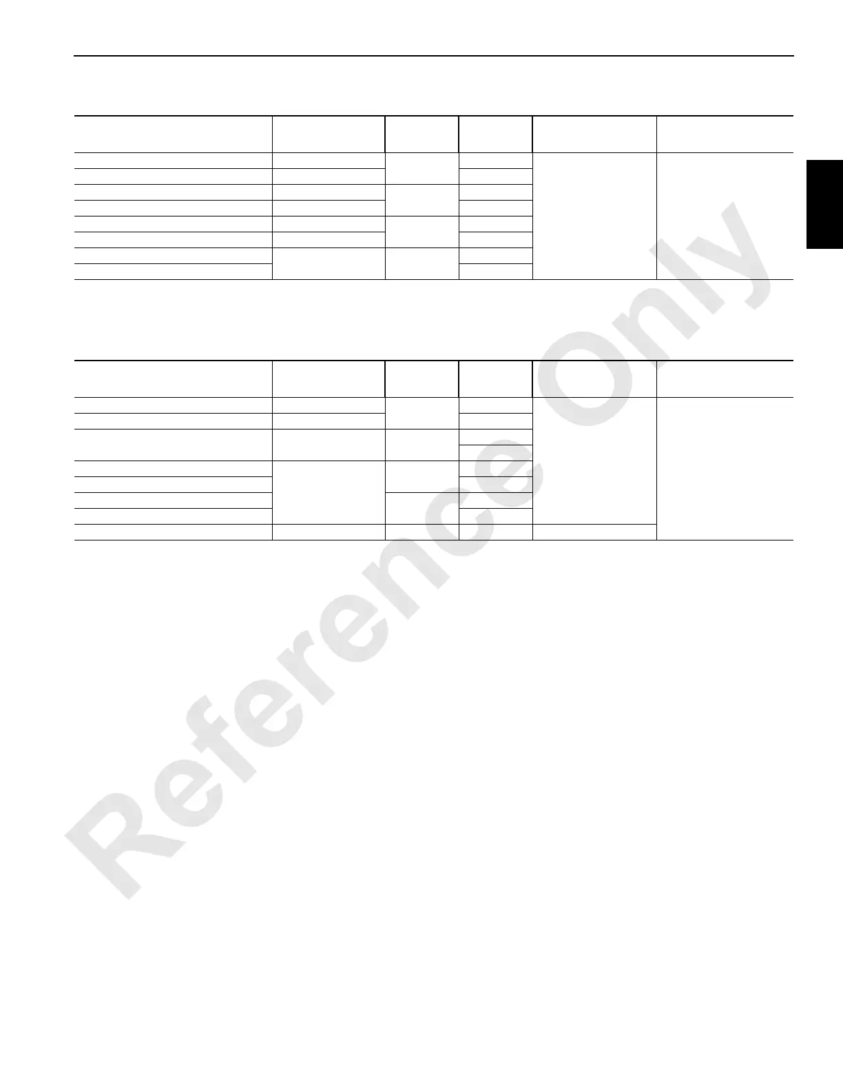
Table 2-1. Closed-Loop Circuit Hydraulic Specifications
Table 2-2. Open-Loop Circuit Hydraulic Specifications
Function
Speed
1
RPM
Pump
Number
Pump
Port
Pressure
2
Bar (PSI)
Charge Pressure
Bar (PSI)
Drum 1 Hoist Up 42 to 46
2
A
420 (6,090) 24 (350)
Drum 1 Hoist Down 37 to 44 B
Drum 2 Hoist Up 34 to 38
1
B
Drum 2 Hoist Down 30 to 36 A
Drum 3 Hoist Up 34 to 38
2
B
Drum 3 Hoist Down 30 to 36 A
Swing Left
1.8 to 2 (one drive) 5
B
Swing Right A
1
Speeds are based on high engine idle, no rope on drums, and handles moved fully forward or back. Speeds can vary plus or minus 5%.
2
Pressures are controlled by relief valves in each pump.
Function
Speed
1
RPM
Pump
Number
Pump
Port
Pressure
2
Bar (PSI)
Charge Pressure
Bar (PSI)
Drum 4 Hoist Up 17 to 19
3 and 4
B
320 (4,641)
NA
Drum 4 Hoist Down 16 to 18 A
Drum 6 Hoist Up and Down 28 to 34 3
A Up
B Down
Right Travel Reverse
5.5 to 6.9 at tumbler
3
A
Right Travel Forward B
Left Travel Reverse
4
A
Left Travel Forward B
Accessories NA 3 and 4 NA 315 (4,568)
1
Speeds are based on high engine idle, no rope on drums, and handles moved fully forward or back. Speeds can vary plus or minus 5%.
2
The load sensing pressure is limited to 320 bar (4,641 psi). The pump compensator pressure is limited to 355 bar (5,148 psi).