Circuit Breakers
(All Models)
All major boat circuits are protected from
shorting and overload by re-settable circuit
breakers. If a problem develops with one of the
following circuits, switch OFF the circuit and
wait for approximately one (1) minute. Then
fully push the appropriate breaker button and
switch ON the circuit. If the circuit continues to
trip, there is a problem somewhere that must be
attended to immediately. See your authorized
MasterCraft service department to resolve this
matter.
The location of the main circuit breaker
board is under the dash panel. In some mod-
els, there is an additional breaker panel to assist with the accessory load, and where
equipped is located near the battery box. There may also be a waterproof fuse for the
stereo amplifier, where equipped. If the boat’s accessories are malfunctioning, check
and then re-set breakers as necessary.
The engines are also equipped with breaker systems. The main 35A circuit breaker
protects the engine electrical system and components from overload. If the engine will
not turn over with the battery switch in the ON position, locate the red breaker re-set
button (labeled “35”) in the engine. There will be an audible click. Try again to start the
engine. If the breaker trips again, the engine requires attention. Immediately take your
boat to your authorized MasterCraft service department.
In addition to the 35A circuit breaker, the engines are equipped with additional com-
ponent overload protection, including a 15A ATO fuse for the fuel pump, a 15A ATO fuse
for the injectors and a 15A ATO fuse for the ECM unit.
If you suspect that any of these fuses may not be operating as designed, you should
take your boat to your authorized MasterCraft service department for inspection and
repair.
If during maintenance or inspection it becomes necessary to remove or re-position
any of the engine’s wiring or wire harness(es), verify that the wiring has been returned to
its original position and that all harnesses are routed correctly before attempting to use
the boat again. If a wiring clip or retainer breaks, replace it immediately. Wiring is spe-
cifically routed to eliminate problems related to engine heat and spray or immersion in
liquids. Electrical problems may result if wiring is moved from its original position!
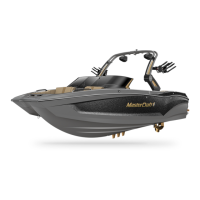
Dual Battery Operation Switch
(All XSeries)
All equipped models: For normal operation the battery switch should be
placed in the ON position. This allows the engine and all accessories to
receive power. The engine will recharge both batteries with the switch
ON. For transportation and storage, the battery switch should be placed
in the OFF position to allow both batteries to be isolated from all circuits.
Note: The switch knob may be removed when it is in the OFF position. This
is a security feature.
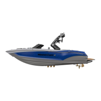
If the engine will not start because the battery is discharged, the en-
gine may be started from the house battery by placing the switch in the
COMBINE BATTERIES position. After the engine is started, the switch
should be returned to the ON position and NOT allowed to remain in the
COMBINE Batteries mode.
Engine Emergency Safety Stop Switch
(All Models)
The engine emergency safety stop switch, which is attached to the lanyard, is an
ignition cut-o switch designed to stop the engine in the event the operator is thrown or
moves too far away from the helm.
2013 MasterCraft Owners Manual • Electronic Instrumentation • Page 3-5
 Loading...