Terminal Test Probe Kit Bosch P/N MM‑ 46523
DTS model shown; mechanical
model similar
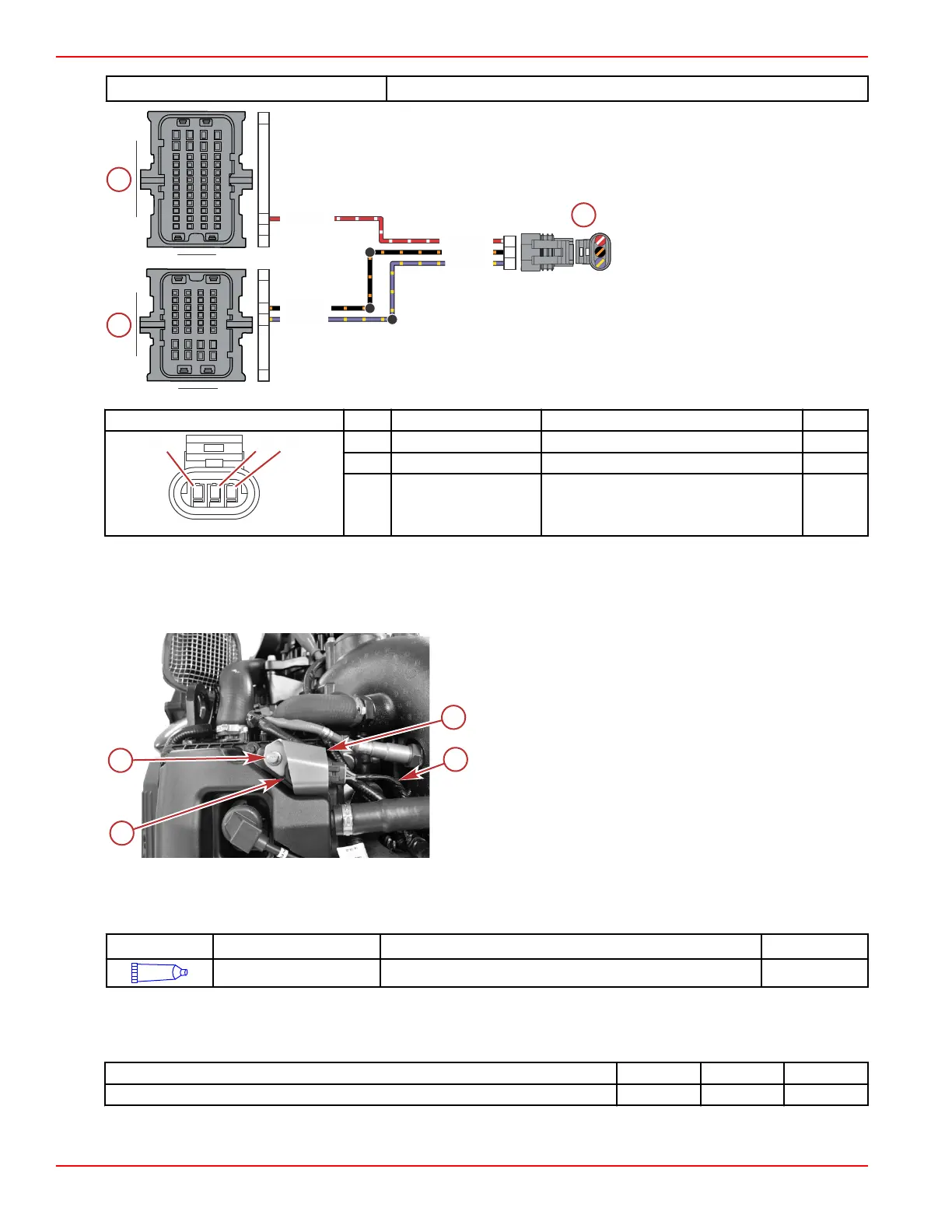
a - Camshaft position sensor
b - PCM connector B
c - PCM connector C
Connector Pin Wire Color Function PCM
A Red/white Camshaft position signal BK4
B Black/orange Sensor ground A (–) CE1
C Purple/yellow Sensor power A (+) CF1
Camshaft Position Sensor Removal
1. Disconnect the sensor from the engine harness.
2. Remove the M6 x 20 screw securing the camshaft position sensor, and remove the sensor and sensor bracket.
a - Camshaft position sensor
b - M6 x 20 screw
c - Sensor bracket
d - Engine harness
Camshaft Position Sensor Installation
1. Apply Extreme Grease to the sensor O‑ring.
Tube Ref No.
Description Where Used Part No.
Extreme Grease Camshaft position sensor O-ring 8M0071842
2. Install the sensor into the valve cover.
3. Place the bracket over the sensor, and secure both items with an M6 x 20 screw.
4. Tighten the screw to the specified torque.
Description
Nm lb‑in. lb‑ft
M6 x 20 screw 8 70.8 –
5. Connect the engine harness to the sensor.
100A
100B
101A
PPL/YEL
BLK/ORN
RED/WHT
RED/WHT
BLK/ORN
PPL/YEL
A
B
C
A
B
C
H4
A1
F1
E1
A1
K4
M4
A
B
C
A B
C
D E F G H
J
K
AB
C
DEFGH
J
K
1
3
2
4
L
M
L
M
Sensors
Page 5A-14 © 2018 Mercury Marine 90-8M0146617 eng JULY 2018
 Loading...


