Meter Test Leads
Meter Scale
Reading
Red Black At 21 °C (70 °F)
Pin A Pin B Auto 78.4–145.6 kΩ
Pin A Pin C Auto 182.0–338.0 kΩ
Pin B Pin C Auto 100.8–187.2 kΩ
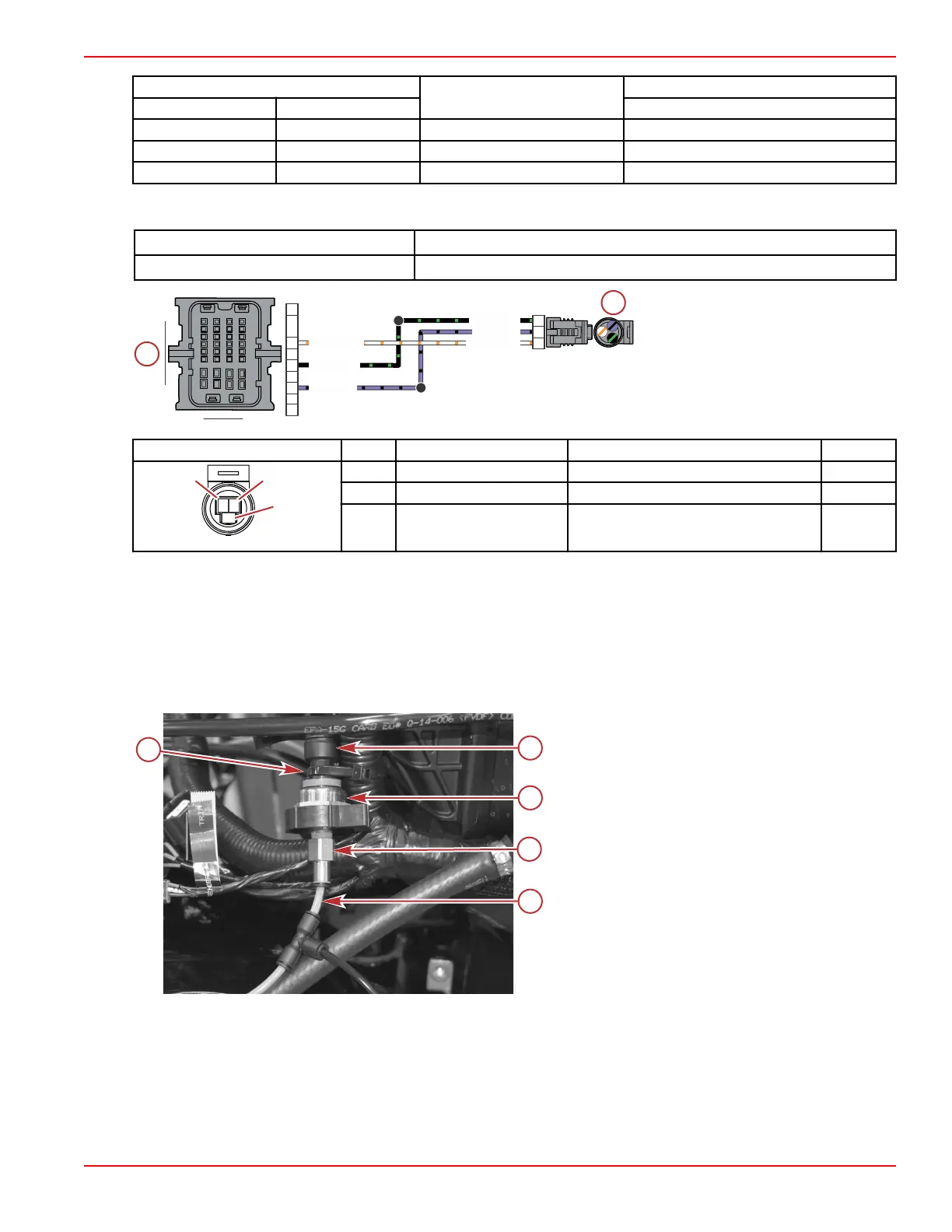
4. Perform a continuity check of the sensor wiring between the sensor connector and the PCM. Note that both the power and
ground circuits have splices.
DMT 2004 Digital Multimeter 91‑892647A01
Terminal Test Probe Kit Bosch P/N MM‑ 46523
a - Pitot pressure sensor connector
b - PCM connector C
Connector Pin Wire Color Function PCM
A Black/green Sensor ground C (–) CE3
B Purple/black Sensor power C (+) CE4
C White/orange Pitot pressure signal CB3
Pitot Pressure Sensor Removal
1. Remove the port intake runner. Refer to the appropriate service manual.
2. Disconnect the pitot tube from the sensor.
3. Disconnect the engine harness connector from the sensor.
4. Cut the cable tie to remove the sensor from the engine.
5. Remove the sensor adapter from the pitot pressure sensor.
Items removed for clarity
a - Cable tie
b - Sensor connector
c - Sensor adapter
d - Flush hose
e - Pitot tube
125A
124A
PPL/BLK
BLK/GRN
BLK/GRN
PPL/BLK
WHT/ORN
WHT/ORN
A
B
C
H4
B3
E3
E4
A1
C
BA
Sensors
90-8M0146617 eng JULY 2018 © 2018 Mercury Marine Page 5A-37
 Loading...


