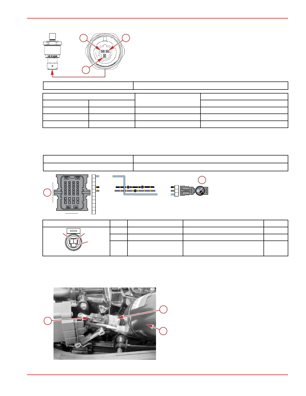
3. Measure the resistance between pins A, B, and C of the oil pressure sensor.
a - Pin A – ground (–)
b - Pin B – power (+)
c - Pin C – pressure signal
DMT 2004 Digital Multimeter 91‑892647A01
Meter Test Leads
Meter Scale
Reading
Red Black At 21 °C (70 °F)
Pin A Pin B Auto 78.4–145.6 kΩ
Pin A Pin C Auto 182.0–338.0 kΩ
Pin B Pin C Auto 100.8–187.2 kΩ
4. Perform a continuity check of the sensor wiring between the sensor connector and the PCM. Note that there are splices in
both the power and ground circuits.
NOTE: The diagram shown below is for DTS models. Mechanical models have only a single splice in the ground circuit,
between the oil pressure sensor connector and the PCM connector. Refer to
Sensor Power A
‑
Mechanical
.
DMT 2004 Digital Multimeter
91‑892647A01
Terminal Test Probe Kit Bosch P/N MM‑ 46523
DTS model shown; mechanical
model similar
a - Oil pressure sensor connector
b - PCM connector C
Connector Pin Wire Color Function PCM
A Black/orange Sensor ground A (–) CE1
B Purple/yellow Sensor power A (+) CF1
C Light blue Oil pressure signal CA1
Oil Pressure Sensor Removal
1. Disconnect the engine harness from the sensor.
2. Remove the sensor from the engine.
a -
Oil pressure sensor connector on the engine
harness
b - Oil pressure sensor
c - Oil filter
100C
100A
101A
PPL/YEL
BLK/ORN
BLK/ORN
LT BLU
LT BLU
PPL/YEL
A
B
C
H4
E1
F1
A1
Sensors
90-8M0146617 eng JULY 2018 © 2018 Mercury Marine Page 5A-31
 Loading...


